Lamda equals to how many degrees on smith chart
Say electrical length BL =30 then
360°-->lamda,
30°--->30°*(lamda/360) so L=lamda/12. So here I am using 360° as lamda. Where am I making mistake?
Why do you switch back to 360°? You are correct that one turn on the Smith chart is lambda/2. That's also shown on the outermost scale, which ranges from 0 to 0.5
https://de.wikipedia.org/wiki/Smith-..._chart_gen.svg
You mentioned physical length. When you convert from electrical length to physical length, you need to consider the effective propagation constant. In most cases that is: physical length = electrical length / sqrt(eps_effective).
Yes I know but by doing this (360°-->lamda, 30°--->30°*(lamda/360), so L=lamda/12) also gives us correct physical length of the line, isn't it? That's what I don't understand.
In the Smith chart, a line with 30° electrical length will turn 60° in the Smith chart. But in transmission, it has 30° phase, of course. And if the line is built from air dielectric, it has a physical length of lambda0*30°/360° where lambda0 is the wavelength in air.

Note the conversion from electrical length (lambda * 30/360) to physical length. Only for lines with eps_r=1, both are the same. For real lines, wavelength in the medium is smaller than wavelength in air, by factor sqrt(eps_effective). So the physical length of a teflon line (eps_r=2.1) must be smaller by that factor sqrt(2.1)
Thanks, I understand. So, as long as eps_r=1 I can use this.
Why is this?
Because the signal travels 30° thru the line, and the reflected portion another 30° on the way back.
That's what seemed unclear in your first question, if the 30° was for the electrical length parameter of the line (S21 angle) or for the rotation angle in the Smith chart (S11 angle)
That is the electrical length I got from smith chart utility, so I think it is the electrical length parameter of the line.
But If I have matched condition, then I will not have reflected portion. In that case, shouldn't it be 30° only?
I hope you meant "Note the conversion from electrical length (30°) to physical length (lambda * 30°/360°)"
I'll stop here, because you seem to misunderstand my posts and my use of the term "physical length".
I didn't see that edited your 1st post. May be I misunderstood but I want to correct it now.
Anyway If you remember from other post
https://www.edaboard.com/showthread....rtuoso-and-ADS
I said that there are these parameters.
1.Electrical length (in terms of lambda)
2.Electrical length (in terms of angle)
3.Physical length
and I also mentioned that "So I always need to convert from electrical length (EL, found in smith chart utility) to physical length(EL*lambda/360) ".
1. I know electrical length (EL) is phase constant (B)* length of the line (l)(this is Physical length as per me, doesn't everybody considers like this, correct me if I am wrong)
2.You mentioned physical length = electrical length / sqrt(eps_effective), I am not sure about this, could you tell how this conversion works.
3.Finally, as I mentioned in the previous post, this is how I convert physical length = EL*lambda/360, which is the point of this thread discussion. Hope I clarified what I am looking for. If you think now I am in right direction then you can reply.
To avoid going in circles, let's do is on your specific example. Please specify
- frequency
- your electrical length in degree
- effective permittivity of your line
That last parameter is important for real world use because the phase delay varies with material, at the same physical length. I guess you don't build a line from air filld coax, so we need to agree on a material to calculate a physical length from a given phase delay.
Wrong.
It is 180degree.
Right. This is round-trip.
Simply you can not understand basic wave equation.
You can not understand oneway-trip and round-trip at all.
S11 and S22 undergo round-trip.
S21 and S12 undergo oneway-trip.
β=2*pi/λ
Oneway trip : exp(-j*β*L)
Round trip : exp(-j*2*β*L), This is a phase rotation in smith chart.
See https://www.edaboard.com/showthread....d-ADS/page2#31
L=λ/4 <-> θ=90degree
L=λ/2 <-> θ=180degree
L=λ/1<-> θ=360degree
No.
However there is no phase rotation actually since Γ=0.
frequency-1 GHz
your electrical length in degree=41 degree
effective permittivity of your line=4.1 F/m
Maybe you misunderstood the question, I asked for permittivity (epsilon_r), not capacitance.
As mentioned above, the dielectric material used in the line will change the propagation speed (cmedium = c0 / sqrt (εr*μr), so it changes the phase delay for a given geometric length! You cannot calculate the physical (geometrical) line length for a given phase delay if that value is missing!

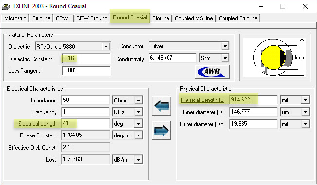
To be precise, I asked for effective permittivity. For lines where all the electric field is in that dielectric (e.g. coax) that's simply the permittivity of the dielelectric materials. For lines where parts of the field is in air and other parts in dielectric, it's a bit more complicated and you want to use a tool like this: https://www.awr.com/software/options/tx-line

I know what you meant from beginning related to epsilon_r. It is my mistake I wrote for epsilon_r= 4.1 F/m in my old report also. So I copied from there directly. I think I can work this out. Thanks.
Useful for people who read it in future. There is a worked out example here https://www.rfwireless-world.com/Ter...al-length.html.
Ok, great!
It seems that some confusion was the use of terms "physical length" vs. "electrical length".
Where I work, we use "electrical length" as described here in "use of term" section 2.: the length of an equivalent line with air dielectric. ("This line has a phyiscal length of 2m and an electrical length of 3m.")
Another source of confusion was your title "how many degrees on Smith chart" which indicates S11 phase, but you where looking for S21 phase.
Lambda in air is 3e8 m/s / 1e9 Hz = 300mm
length of line assuming air dielectric: 300mm * 41/360 = 34.17mm
length of line assuming er=4.1: line length 34.17mm* sqrt(4.1) = 16.88mm

The image is taken from MICROWAVE AND RF DESIGN: A SYSTEMS APPROACH by Michael Steer. He uses the same way what I used. Say Figure 1.

*Taken from https://nptel.ac.in/courses/11710105...s%202/5.3.html. Say Figure 2.
Indeed, the rotation on smith chart is 360°, when the length of the line is lamda/2.
Makes sense to me now. As in the attached figure2, 2Beta*l=2*pi, which is two times electrical length.
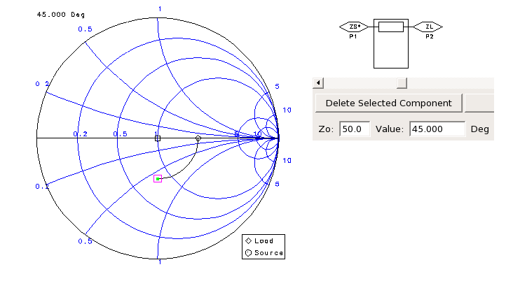
I moved 90° on smith chart and it added line with 45° EL. This is what I missed earlier.
I don't know whether I can say this here or not. This is off the topic, @ volker@muehlhaus. This is one of the documents I read on Transmission line http://muehlhaus.com/wp-content/uplo...sion-Lines.pdf. Because of this document and from your user name, I realized that you work there.
Surely learn Oneway-Trip and Round-Trip.
1 Ghz - 30 cm wavelength in air Epsilon = 1 -- 15cm wavelength in FR4 Epsilon= 4
1/sqrt(4) = 1/2 will be the velocity of wave in FR4 when compared to Air.
Electrical length in terms of S11,S22 ( Insertion loss, Return Loss) : A wave goes to the input matching, or output match of an active device and "reflects", in that reflection the wave traverses the distance twice; hence round-trip, hence double the length of the trace.
In terms of S21, S12 ( Forward gain, reverse gain). A wave goes through the active device, while gaining power or being attenuated in power, no reflection, just pass through; hence normal length of the trace.
You can not understand very basic things at all.
Consider V and I which are located at L=λ/2 separation.
V(x=λ/2) = -V(x=0)
I(x=λ/2) = -I(x=0)
Phase differece for L=λ/2 is 180degree not 360degree.
On the other hand, Zin=V(x=λ/2)/I(x=λ/2)=V(x=0)/I(x=0)
So Zin and Γin are same as values at x=0.
That's all.
He wrote "rotation on Smith chart" which is correct, as it refers to S11.