Seeking wiring advice for Wifi router
I've built a few Wifi antennas in hopes of drawing in a signal from a few dozen meters away. I've had trouble figuring out how to translate the output from the antenna's SMA connector to my computer. I tried a cheap USB dongle, but it doesn't play well with linux (also didn't work on my windows drive for some reason, but worked on a friend's). I then got help on a few router models without success. So I bought a used NetGear model.
I hope to ask your help learning how to wire the SMA connector from the ActionTec model into the NetGear circuitboard. But the Actiontec has both wires of the same color, so I can't tell which is positive & which is neutral.
(It seems like this is a grey area since antennas don't actually send power, but one wire goes to the centre pin and one to the outer braid)
( https://www.youtube.com/watch?v=Mp96xNic7ho )
I've included all files both overall and close-ups here - http://towardzeroimpact.net/Wifi/
Once again thanks in advance
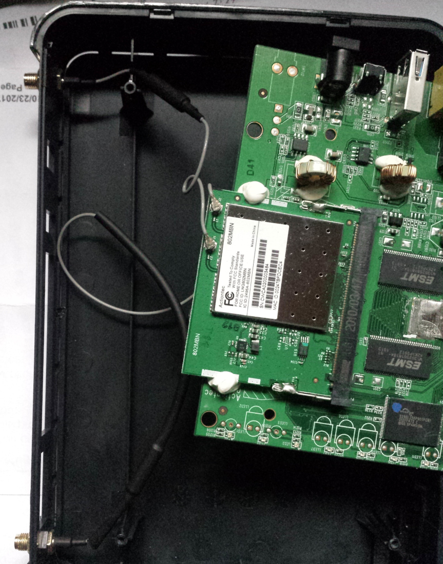
You are apparently misunderstanding things. The WiFi adapters have two antenna ports for diversity purposes, each coax cable will be connected to a reverse SMA jack and an antenna. If you have only one antenna, you should check the module documentation which port is specified as main port and connect it.
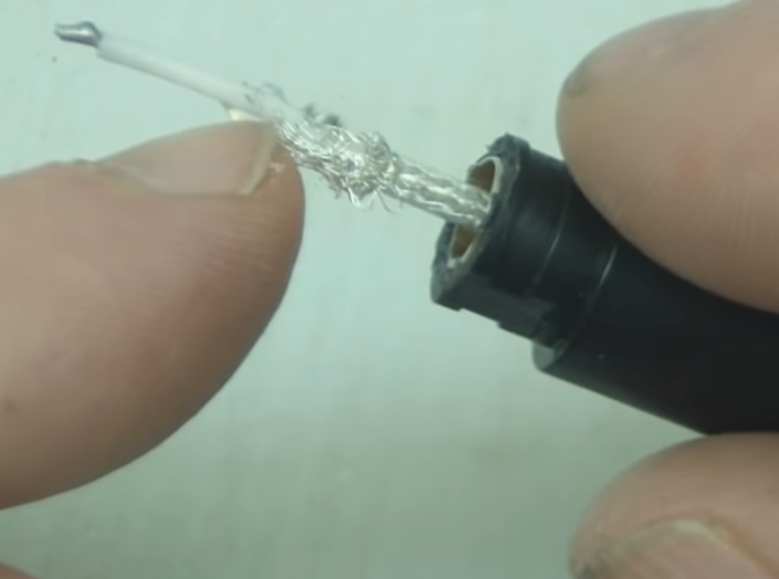
I would respectfully disagree with FvM on this. Each dipole antenna has two very tiny wires coming from it. As with laptop chargers and USB plugs, the two wires are wrapped around each other with insulation between, making it look like a single wire.
The video describing the dismantle is here - https://www.youtube.com/watch?v=m44sB7Ppt3M
What I would love to learn is which two contacts on the board are the attachment points for the antennas.
Thank you in advance.
Disagree with what? That both adapter ports J1 and J2 are small coaxial jacks and the gray cables shown in the post #1 photo are miniature coaxial cables, similar to the cable shown in your latest post, only much smaller?
See below a product photo that shows the coaxial connectors and adapter cables
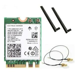
Each coaxial connector has a center signal pin and an annular ground pin, mating the small jack at the adapter cable.
Sorry FvM. It sounds like what you're saying is that each of the ports (J1 & J2) are connections with two separate contacts just like the RP-SMA jack. That makes sense. Would you be willing to post a larger-res version of that image? I've been unable to find a picture which shows the board and the connectors.
The cables are, exactly as FvM stated, the antenna feeds. You can see exactly where to connect in the top right corner of the board in the photograph. They both carry 2.4GHz RF to/from the antennas. There are two cables, one to each antenna. There is no 'positive' or 'neutral', they both carry essentially the same signal. The cable construction is called co-axial, it has an outer screen and inner single conductor, the braided wire is an electrically equivalent but flexible version of a solid pipe with a centrally mounted conductor.
Not surprising, they do not connect together , they only carry the signal from the WiFi transmitter/receiver to it's antennas. There is nothing on a computer that matches the frequency or voltages on the cables. The link to a computer has to be 'over the air' to a similar router or Wifi access device.
Brian.
A WiFi standard connector is Hirose K.FL2 https://www.hirose.com/product/series/K.FL2?lang=en
Also I-PEX MHF 4 series. Ready made pigtails are available on the market.
The connector is specified in the PCIe M.2 standard for plug-in modules.
20 years ago Murata introduced first these type of connectors.
They are cheaper and better performances than Hirose one (works up to 12GHz).
https://www.murata.com/en-eu/product...econnector/jsc
According to datasheet, JSC receptacle is smaller than M.2 spec and doesn't fit usual WLAN PCIe modules.