Problem with parameters for microstrip PBF simulation in IE3D
I use IE3D for sim. of microstrip PBF , I got confused with the parameters which i should apply in the window, mainly the passband, stopband and center freq. .
Following the window design
waiting

thanks
The stopband edge frequency fs, passband edge frequency fp, and center frequency fc follow a rule: fs<fp<fc. In other words, for f<=fs, stopband antenuation>=XdB (e.g., X=20), for fp<=f<=2fc-fp, insertion loss ripple<=YdB (e.g., Y=0.2), and bandwidth (BW) =2(fc-fp). The assumption is that for f>=2fc-fs, upper stopband antenuation>=XdB.
Hi ,,,
thank u for explination , could u plz explain more using graph (fre. respons of a filter) assigning where fc,fc,fp. For exp. for design of BPF with f1=2Ghz and f2=7Ghz, ?
As I know, f1<fc<f2 ---> fc=√f1f2 ?
thanks
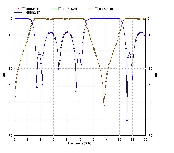
Here is a plot of microstrip parallel-coupled bandpass filter in FilterSyn --- an IE3D Library Module.

Hi,,,
When I design a filter , as i specify the band pass filter parameters, the sim. results show another pass band to the desired one? It is look like as repeating the pass band ? ?(after 13.8GHz) do u konw why and how to stop other bands ?( just desired pass band)
help.
thankx
Hi, mohazaga:
Repeating similar performances in the frequency is always the case for microwave filters unless you do something special to surpress some special ones. You can't even suppress all of them. Overall, it is always repeating in frequency because it is the nature of waves.
Regards,
Hi ,,,
How we can suppress those frequencies out of passband?
Also, how we can determine or change the stripline (conductor) thickness?
(I don't figure out how in IE3D, it's just give me Strip Type : .... ?)
Thankx
Hi, mohazaga:
1. To suppress it, you may have to add more elements in the structure. You may have to do it on the IE3DLIBRARY or MGRID layouts. The FilterSyn is a library based synthesis program. You can go beyond the implemented models available from the list.
2. For the metallic types, they are defined in the Basic Parameters of IE3DLibrary. I don't see any button to access it inside FilterSyn's dialogs. You may need to define them outside the dialogs in the main window of IE3DLibrary.
Best regards,
Hi ,,,
thank u for reply, well, adding an element to suppress the out band signals by means of another filter or what? do u have any idea?
About the conductor strip thickness, as i see there is no way to fix it ? Where we can do that in IE3D ?
thankx
Hi, mohazaga:
There used to be the Basic Parameters dialog. However, due to some potential conflict between the unit defined there and the unit defined in this dialog, the Basic Parameteres is removed. Metallic types are defined in Basic Parameters. At this time, you can create the filter onto IE3DLIBRARY. Then, you can access Edit->Basic Parameters to change it. There will be a fix for it. Regards,
Hi ,,,
could u explain in more details using IE3D parameters. I incloud the IE3D windows
to explain the variables they used in sim.


thankx
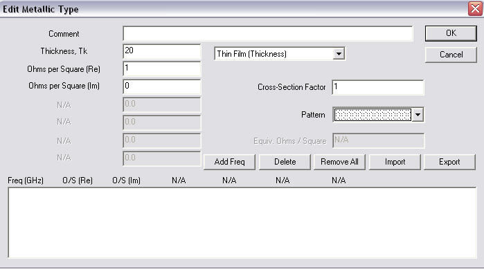
Hi, mohazaga:
For the 3rd picture when you are prompted to enter a metallic type, please select Normal type instead of the Thin Film type. Then, enter the thickness and the conductivity. Other parameters are not critical. You can define a list of metallic types. Then, you can pick which one you want for a filter inside FilterSyn.
Regards,
Hi,,,
Thanks for help . by the way what is the default values of the NORMAL type which they are used in IE3D? (by means of metallic strip type and it's thickness)
thanks alot
Hi, mohazaga:
What should be the conductivity and thickness? It really depends upon what material you have. For the thickness, it is really hard to say. Many PCB uses half oz and it is about 0.7 mils for copper or 1 oz for 1.4 mils. It is normally much thiner for MMIC application. For conductivity, gold is 4.9e+7 or some people use 4.55e+7. Copper is supposed to be about 5.88e+7. There should be some variations. You do need to check the spec sheet of your material for the parameters. Thanks!
Hi,,,
thank you very much for reply and great information but just I'm concerning the default values of the NORMAL type which they are used in IE3D? (by means of metallic strip type and it's thickness). Since I sim. and I got the result but I want what the parameters of conductor they used as default in sim. .
thank x alot
Hi, mohazaga:
What parameters should you use, it really depends upon the reality. There are different materials available. You need to enter the ones matching your reality. For some applications, metallic loss can be very critical. For some, they may not. Normally, narrow bandwidth and high frequency structures are affected more.
Best regards,
Hi ,,,
The basic parameters for the filter which i design is as in next fig. . I want to figure out the metallic strip thickness?. I just specify the substrate type and thickness where IE3D normal setting of metal strip I use . I don't specify the strip thickness.

help plz
thankx
Hi, mohazaga:
There are 2 default types defined. You can double click at any one to change it. In the dialog for the filter, you just pick which metalic type you want.
Regards,
Hi ,,,
so , i have to chose Metallic strip type No1 or No2?
but I already sim. , which type it's used by default when its sim.?
Ok, What is the meaning of type parameters ( TK, TanD(E), ... .)
thankx
Hi, mohazaga:
Please read the chap3.doc of the IE3D USER'S MANUAL. It is in the installation. Regards,