HFSS Mutually Coupled Inductors
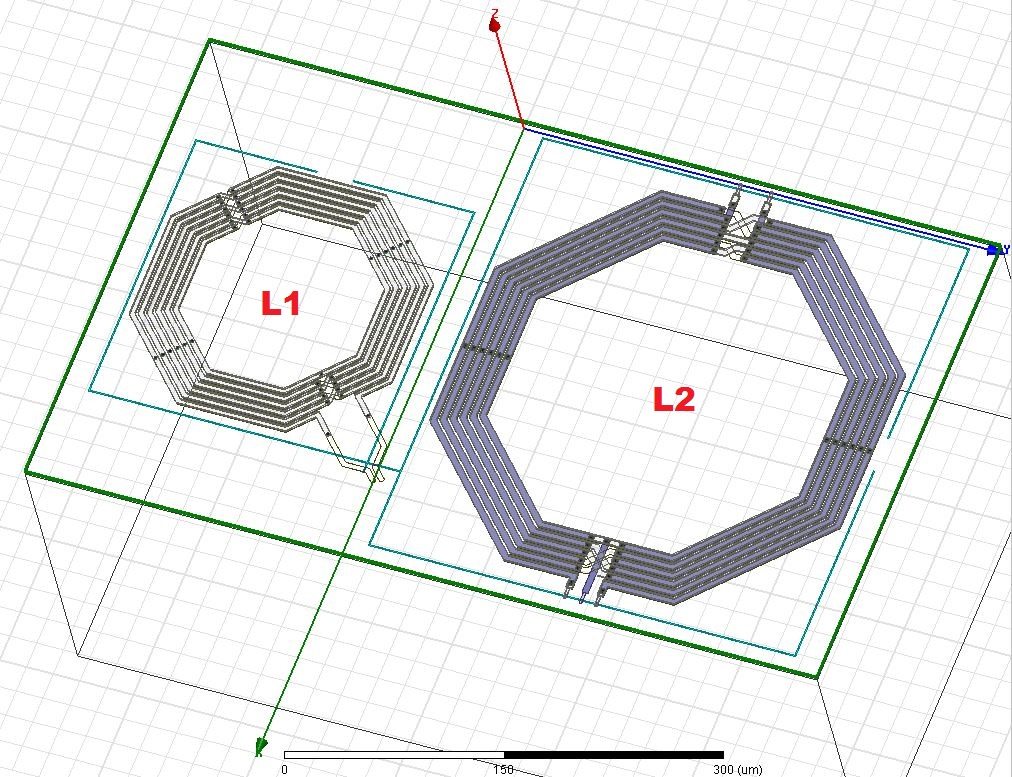
I have a model in HFSS that contains two coils (L1 and L2) separated by a distance as shown in attached picture. The solution type used is Driven Terminal and I have excited all the terminals with 50 ohm Lumped ports. The whole structure is enclosed inside a radiation boundary (air).
Now what I am trying to do is to simulate mutual coupling effect on Coil L1 due to L2. I have simulated S-parameters for both cases, i.e with and without Coil L2 but the results are same. The self inductance of both coils is computed fine but it seems like HFSS did not account for mutual coupling effect. So may be I am missing something as I have very little experience in using HFSS.
I will greatly appreciate any help you guys can provide to solve this issue. Thank you all

Does the enclosing air box extend outwards on both sides of the inductors (along the z axis)? From your image, it appears that it only extends on one side (in negative z).
HFSS will account for the mutual coupling -- how much are you expecting in this orientation?
I appreciate your prompt response. Well sorry for the confusion. Yes, the air box is extended along each axis which is not shown in the image. The negative z box represents substrate material.
I am expecting a slight shift in frequency due to coupling effect when simulating S-parameter in LC tank circuit configuration but I keep getting same results.
If the simulation setup is proper, then there must be negligible coupling. Ensure the setup is adequately meshed -- you probably want at least 2 cells in the inter-trace gap widths.
Hi PlanarMetamaterials,
The meshing is effectively done by running multiple passes and I can see the convergence. Can you please elaborate more like what exactly do you mean by saying the need for 2 cells? Do I have to put some extra planes etc or something in between both structures in order to see the coupling effect?
Thanks for your assistance.
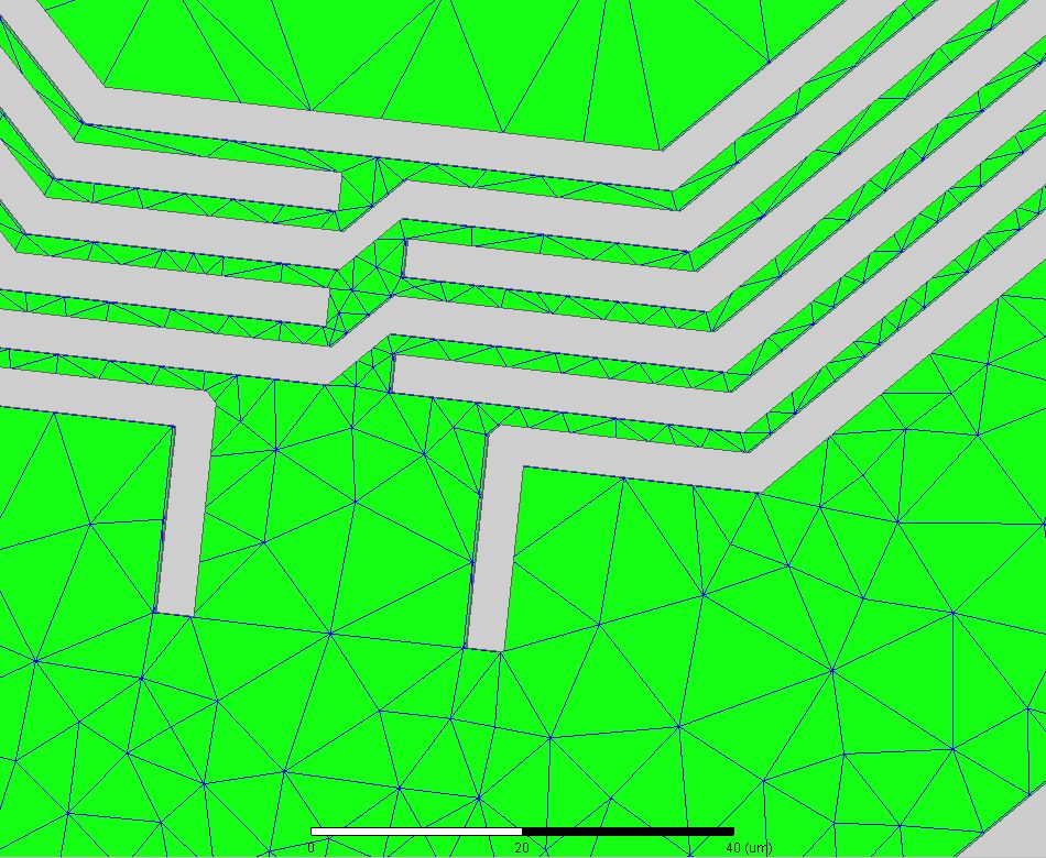
Roughly speaking, I've found that a simulation with multiple parallel traces is satisfactorily meshed where there are at least 2 tetrahedral mesh elements in between adjacent traces. I assume you're evaluating coupling from S12/21?
Thanks for your elaboration, that explains a lot. I have defined sufficient model resolution under Mesh Operations and have inspected elements by plotting Mesh. The Tetrahedral geometry in between trace gaps appears to be one box or cell as shown in attached figure. Is it an acceptable number for accurate simulation or do I have to increase Mesh refinement or resolution etc?
Yes I am using 2-port S-parameter for evaluating Inductance value for L1.
Regards,

What k factor do you get from HFSS results?
Hi volker,
I haven't calculated coupling coefficient or k factor for that inductor pair. What I am experiencing during physical measurement is a slight shift in frequency (around 70 MHz) across L1 when I turn-on the coil L2. May be something else is causing the drift but I need to know if mutual coupling is also playing its part or not.
Thanks
I'd aim for a bit higher density if possible, just to be sure that convergence isn't an issue.
Then it would really make sense to calculate mutual coupling, or k factor, or change in inductance with the second coil open/shorted. From your post, it is difficult to understand what you have simulated (what ports where) and how this was evaluated.
If you have one differential port for each inductor, coupling factor is k=sqrt(1-1/(Z11*Y11))
For inductance with the second coil open/shorted, evaluate L from Z11 and Y11 and see what the difference is.
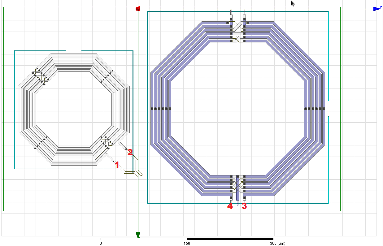
Sorry for the late reply man. Ok let me explain what I have actually simulated. I have excited all terminals with 50 ohm lumped ports. The reference conductor is same metal for all ports. I have pointed the location of four ports in the attached picture. Also I want to mention that I haven't defined differential pairs on Excitations (may be that is causing a problem?).
Regarding k factor formula, how can I input Z11 and Y11? I mean it should be like Re(Y11) or Im(Y11) etc. Correct me if I am wrong because I'm unable to provide this function in HFSS Terminal Solution Rectangular plot.
With thanks and appreciation,

Sorry, I am not an HFSS user, so I don't know what capabilities the display tool has.
For the coupling, I would simplify the model from 4 ports (global ground ref) to 2 differential ports (your 1-2 and your 3-4). To create the Y and Z-params from S-params, I don't know how to do that in HFSS.
No problem my friend, thanks for your help. Well HFSS does support Y and Z parameter and the reason I was asking about the formula is that Z11 and Y11 are vector quantities while k factor is scalar. There should be something like Mag, Re or Im etc in that formula right?
I will try simulating differential port setting and see if that works.
Also to further explain my approach, I am exporting 4-port S-parameter touchstone format from HFSS and importing that file in N-port network simulation (Cadence Virtuoso) to see the resonant frequency of Coil L1. Am I doing it the right way? I am pretty much convinced that S-parameter file contains sufficient information about circuit model like inductance, coupling etc.
Thanks again for your assistance...
No, it looks like k can be a complex number in theory.
Yes, in general the 2-port-per-inductor simulation is fine, as I described here:
http://muehlhaus.com/support/ads-app...uctor-em-ports
Just take care to remove the artefacts from this port configuration where you connect to global ground. I have seen the HFSS support guys create nonsense results because their lumped ports in FEM introduced extra inductance (due to fionite size of ground path), which was never removed from simulation results.
Hi Volker,
Thanks for sharing your article, it helped me to better understand port configuration. Now, I have re-run the simulation by simplifying to 1 differential port per inductor. The k factor is calculated by using formula mag(sqrt(1-1/(Z11*Y11))) and is found to be 0.0311 (at 2.5 GHz).
As you suggested, I have also evaluated inductance from Z11 and Y11 and results at 2.5 GHz frequency are as follows,
Im(Z11)/2*pi*freq ---------> 12.2 nH
-1/(2*pi*freq*Im(Y11)) ---> 12.7 nH
How can I relate this information with actual measured results in which I am getting positive frequency shift when I turn on the second coil?
Regards,
Ok, so at least you now have some coupling, as expected very small.
Your inductance from simulation increases when the second coil changes from "open" to "shorted". Is that what you mean by "turn on", or isn't there more circuitry at the second coil (more than a switch) that might interact with the oscillator?
Assuming that there is more circuitry at the second coil: Have you tried using the k factor information in your circuit simulation, to see what that does?
I have gone through a simular case for a customer, but with > 10 inductors on a chip, all included in the Momentum EM simulation. That's challenging, but what else can we do if the coupling matters?
Hi Volker,
Yes, from HFSS simulation it shows an increase in inductance when Coil L2 is shorted. While in physical measurement as I previously stated, the L1 seems to decrease (might be due to coupling) which results in increased resonant frequency. I assume that this is due to the simplified model which only contains 2 ports.
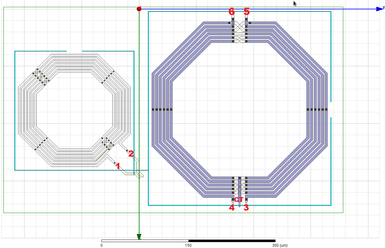
I had been keeping it very simple due to my lack of EM expertise but I think the frequency shift behavior is rather complicated. What I didn't specify is that the second Coil L2 is actually a Balun transformer. As you suggested, I have simulated two port network and evaluated k factor by using open/short formula but how can I implement same approach with multiple port network? I mean the Balun itself contains 5 ports (primary, secondary and one centre-tapped, see attached figure).
I would greatly appreciate any help you can provide, many thanks and regards.

And I guess the current in this transformer is somehow related to (correlated with) the first coil's current? Then indeed we need to include this in circuit simulation, to have correct amplitude & phase in both coils.
To get started, I would keep it simple and start with an approximate model. I assume you have a circuit simulation, with some circuit models of these inductor and balun. One way to include couplings is this: add coupled inductors (eg. L1 and L2 with coupling factor k) to your circuit, and the insert uncoupled inductors with negative value (-L1, -L2, no coupling) in series. This way, you have added the coupling mechanism without changing the path inductance.
For the balun, which itself is a tightly coupled inductor pair, not sure if the coupling to an external (third) coil changes with the load. I think it does, an I think yourHFSS model was with open circuit on the secondary. So you might need to extend the model to include coil coupling from balun primary, and coupling from balun secondary. An educated guess is that coupling factors of primary/secondary to the third coil are about the same.
As an alternative, there are SPICE model generators that can create SPICE or Spectre models from n-port S-parameters. But in that case, all your inductor modelling (including loss) need to be very precise, because then we really replace the full inductor/balun models by EM data, and not just add coupling.
Create some output variables like the following:
L1 = im(Z(1,1))/(2*pi*freq)
L2 = im(Z(2,1))/(2*pi*freq)
M12 = im(Z(2,1))/(2*pi*freq)
k = M12/sqrt(L1*L2)
You should be able to just copy and paste those lines into HFSS results window actually. Assuming port 1 is attached to L1 and port 2 is attached to L2, and that there are only inductive elements inbetween. This k is real number and is only a measure of reactive coupling (may be negative or positive depending on orientation). Also make sure you are not simulating past the SRF (self resonant frequency) of your coils.
