HFSS far field 3D radiation pattern
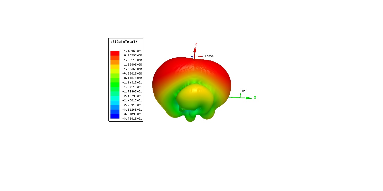
I have simulated a dipole antenna on ground plane for both flat surface and curved surface. But, the 3D radiation pattern is asymmetric and shows directional at theta = -40 instead at 0 degree which doesn't make sense to me. I am expecting more radiation at zero degree that is normal direction to the substrate. Can anyone help me?
Can you attach the HFSS project ?
Hello
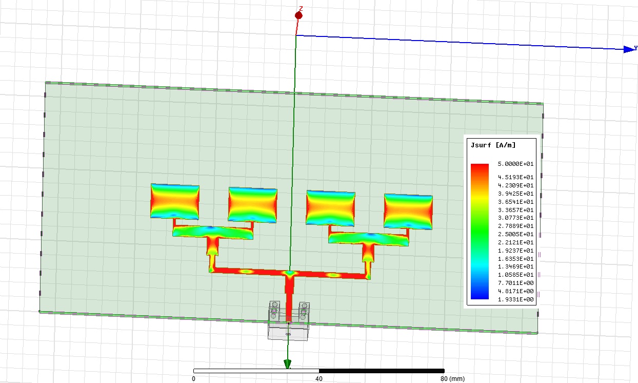
I can't upload the hfss file here. I have attached the current density and radiation pattern pic. Though the current density is symmetric for the 2 pairs of dipole, the radiation pattern 2 lobes are not which I am not expecting.
Could you please help me in this regard and also how to upload the hfss file here.
Thanks!
At the bottom of the Quick Reply pane click on Go Advanced, then click on the paper clip icon (next to the smiley icon) and that will bring up the File Upload Manger.
Hello
The hfss file is attached here. Though the current density is symmetric for the 2 pairs of dipole, the radiation pattern 2 lobes are not. The radiation pattern is more at theta = -40 degree than it is at theta = 40 degree. I am expecting 2 peak symmetric lobes of gain at both sides of theta = 0 degree or a peak gain at theta = 0 degree.
I applied the same design on a curved surface which is not attached here, but the same thing happens. Can anyone help me explaining this.
Thanks
An asymmetrical radiation pattern is well expectable due to the radiation of the feed line structure.
Could you please tell me how can I remove the feedline radiation in hfss. The feedline are not supposed to radiate.
The patch current distributions are symmetric on all the patches.