ADS rectifier simulation "Convergence error" (Urgent help please)
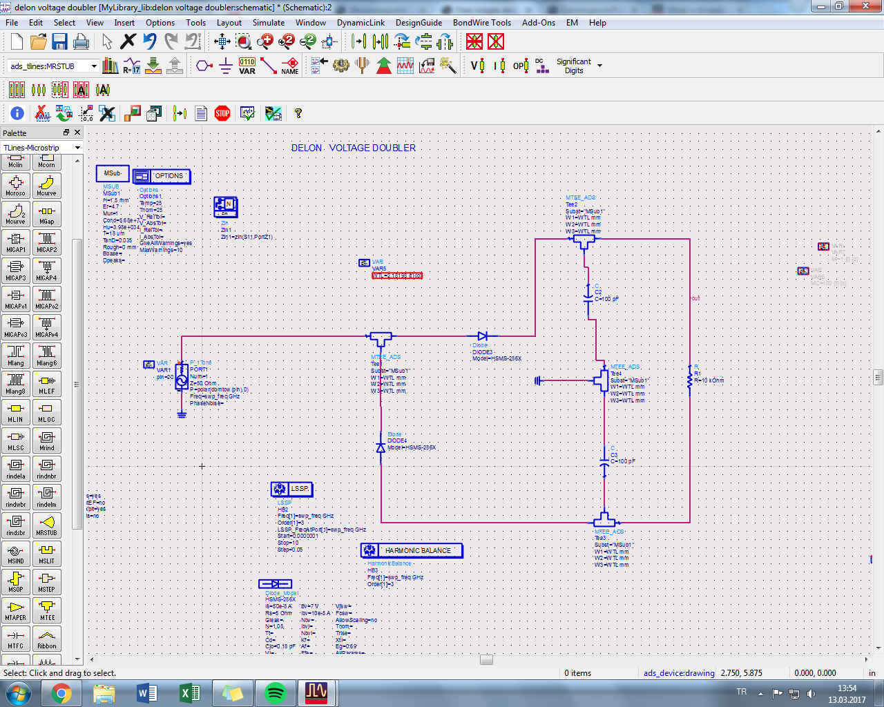
I am trying to do rectenna at 1.9 Ghz with ADS, in rectifier part, i am taking "No convergence" error which is attached in figure 1, and my circuit also added in figure 2. Here is my questions;
1. What is this convergence error in ADS? What does it mean?
2. How can i fix this error?
ps. I am new with using ADS and designing Rectifier. Therefore i need help.
Thanks in advance.

Connect 1Tohm between resistor and ground.
Putting two capacitors in series is not necessarily an error in hardware, but a simulator might have a problem calculating an RC time constant. Try installing a low-ohm resistor inline with each capacitor.
Wrong.
These capacitors are not series connection.
These are no more than grounded two capacitors.
This is true for your previous post.
https://www.edaboard.com/thread363040.html#4
You are correct about the capacitors. It should not generate an error in the simulator. However we can't always be sure what condition prevents a simulator from finding convergence. We can only try various 'tricks' in an attempt to make it behave.
I suggest separating the capacitors. Give each its own ground connection. Then the simulator cannot think they are plain capacitors in series.
I agree with your suggestion to install high-ohm resistors between components and ground.
I see a series stack of caps and MOS gates that has no
DC path to ground in several spots (unless your MOSFET
model has gate tunneling leakage, which is not that likely).
Now I have no idea about ADS harmonic balance simulation
but you might check whether it's using a good DC (OP)
solution, or has tried to make its own and perhaps ignores
the settings which might be helping a DC solution (gmin
etc.). Maybe you can get a DC convergence manually
and force it to be used explicitly. But the error message
is not really enlightening, and maybe the "no convergence"
is some other thing than the DC solution (for example PSS
fails when cycle end mismatches cycle start, such that
"period" is not "steady state").
Thank you so much.
But i need to ask something, i am new about designing thing, in real life i will print this rectifier in FR4 pcb. If i put 1Tohm resistor, will it affect my rectifier's matching section,efficiency etc ? (Matching section which will be used to match with microstrip antena)
Thank you so much, i ll try this.
Thank you for attention, it is my inexperienced but, i could not understand "DC path to ground in several path" what do you mean ?
On closer inspection it looks like I mistook those "tees" for
MOS capacitor symbols.
* Another trick is to install high-ohm resistors across diodes. This relieves the simulator of deciding about threshold conditions as to whether a diode turns on or not.
* Also try splitting your voltage doubler into two half-wave power supplies (one positive, one negative). Problems should be simpler to solve. Get each section working properly, then merge them together.
Thank you so much for your answer.
I am wondering when i add the High ohm resistor across to diodes, ADS can solve easily however, i ll implement this rectifier on FR4, so there will be no high ohm resistor on PCB, i kindly ask for your opinion, when this rectifier on FR4 without High ohm resistor will give same eff and vout value with same with ADS circuit(With high resistor) etc.?
You don't have to add high ohm resistor across to diodes.
As I posted in https://www.edaboard.com/thread365391.html#2
Add 1Tohm between bottom of R1 and Ground.
Yes.
FR4 gives 10~20Gohm resistance.
Less than 100Gohm at most.
rectifier ADS simulation 相关文章: