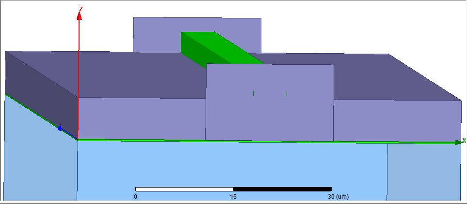
Microstrip Port Excitation
2) Underneath the signal line is dioxide dielectric
3) Beneath the dioxide is ground plane
4) Underneath the ground plane is substrate.
Q: I am using lumped port excitation for this model. Is the rectangular sheet correctly placed (on the top edge of the ground plane)?
Q: How to find Q-factor of this model in HFSS?
I assume this is HFSS. You may want to extend the sheet to cover the lower conductor, as well as extend it upwards past the top of the microstrip some more. Otherwise, it looks OK. The best way to tell, though, is by viewing the modal fields the port generates.
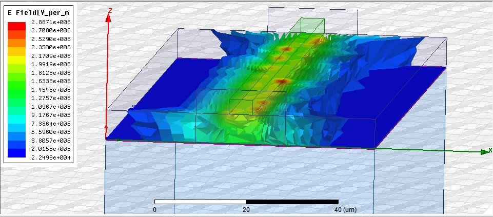
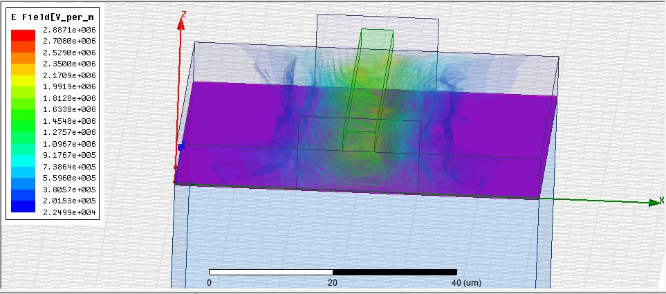
Here are the E and H fields for the above microstrip model. I want to aslo know.
1. How do we ground the substrate in this model
2. How to find the Quality factor of this model?
Field plots that show strongly asymmetric results for a symmetric line mean that results are not accurate (mesh too coarse).
The accuracy of conductor loss is not visible in field plots.
This is the second thread where you ask about "Quality factor" of a line model. Quality factor is a fixed term, often used for inductors, capacitors, resonators. It's not used for lines, so what do you mean by Quality factor here? Microstrip resonator or just accuracy of results or what?
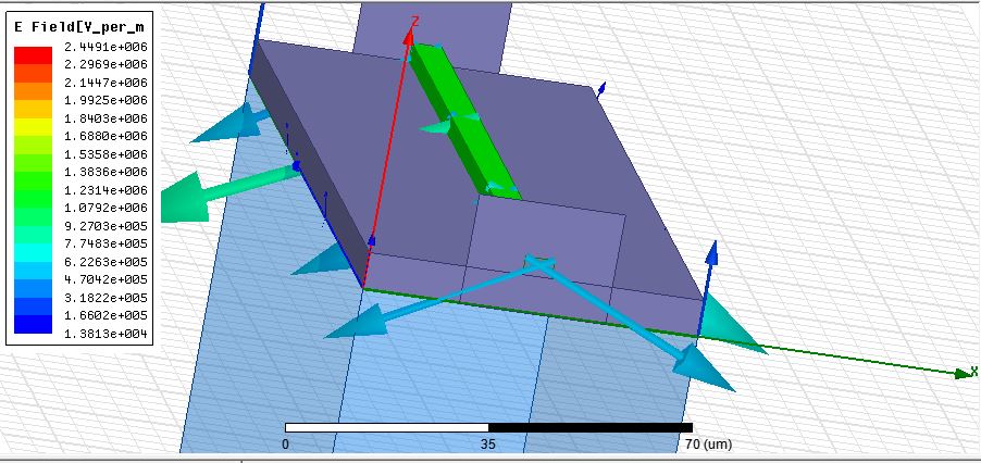
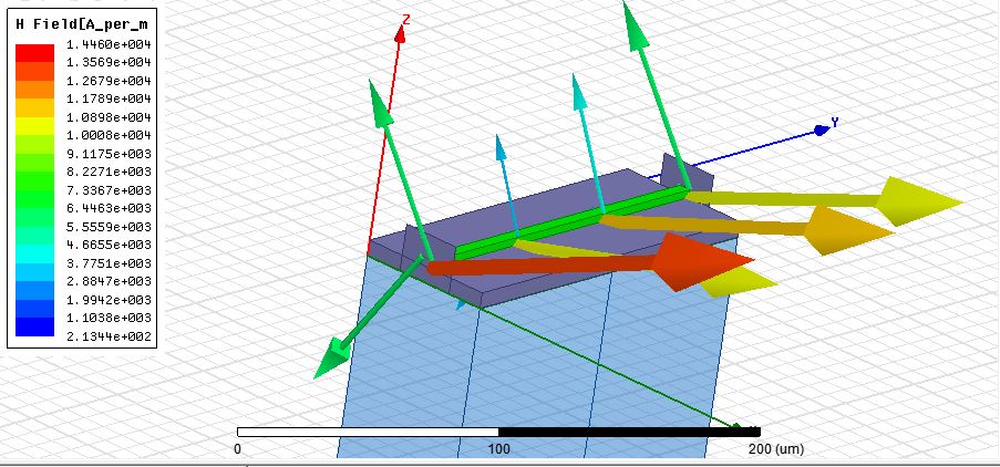
These are the directions for E field vector (between strip and ground) and H field vector (around strip). Are these correct?
Microstrip Port Excitation 相关文章: