Confused - transmission line component in Virtuoso and ADS
I am learning to design matching network with distributed elements. Usually when we design stub matching, we get the line lengths from smith chart. Now when I look at TLIN in ADS it has parameter E(electrical length) and TLINE in virtuoso has delay time. In ADS's smith chart utility also angle (I guess it is electrical length ) is given when stub or line are chosen as matching element. I know there are mathematical relations among these parameters but I am confused why they are not consistent. Someone please clarify. Thanks
Cadence Virtuoso is a Design Framework.
This does not make sense at all, even if you mean "analogLib/tline".
Use correct terminology.
"analogLib/tline" is a just symbol.
It is used by various simulators, e.g. Keysight ADSsim, Synopsys HSPICE, Cadence Spectre, etc.
What simulator do you use from Cadence Virtuoso ?
You can use Keysight ADSsim from Cadence Virtuoso.
If you mean Spectre Primitive, "tline", it is derived from SPICE which is oriented for signal delay originally.
That's all.
HSPICE Syntax
Ideal T-element Transmission Lines
Syntax
General form:
Txxx in refin out refout Z0=val TD=val [L=val]
+ [IC=v1,i1,v2,i2]
Txxx in refin out refout Z0=val F=val [NL=val]
+ [IC=v1,i1,v2,i2]
On the other hand,
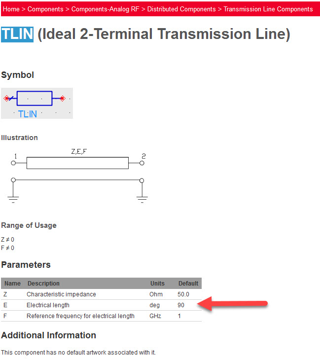
TLIN (Ideal 2-Terminal Transmission Line)
TLIN4 (Ideal 4-Terminal Transmission Line)
in ADSsim are oriented for RF application.
I am using spectre simulator but mostly I never used HSPICE syntax or something, I only use GUI.
I see so analoglib/tline is used, if I want signal delay. Actually I am solving the from boook Microwave Transistor Amplifiers analysis and design, 2nd edition by Guillermo Gonzalez. So I am stuck on how to solve it using smitch chart utility in ADS to find those line length and implement the schematic in Virtuoso.
What do you want to mean ?
Surely see "spectre -h tline".
Fisrt of all, what is your operating frequency ?
Attached figure is Spectre Syntax.
Surely see "spectre -h tline".
Specify z0, f and nl.
Let's take 1 GHz.
You didn't yet clarify where you see inconsistency of different parameters (electrical length, delay, phase angle) used to describe transmission line circuits. As you state, they are clearly related.
His purposes are satisfied if he set z0, f and nl instead of z0 and td for Spectre Primitive, ?tline?.
It's based on users needs. ADS users are usually RF designers, so they don't think in terms of delay time. That's why ADS ideal line models are based on phase delay at a given frequency.
This makes sense, So I always need to convert from electrical length (EL, found in smith chart utility) to physical length(EL*lambda/360) and use it in analogLib/tline.
Thanks, your comments are valuable. is this normalized electrical length equal to electrical length ( in terms lambda)/ lambda ?
Finally, I understood there are three parameters ..
1.Electrical length (in terms of lambda)
2.Electrical length (in terms of angle)
3.Physical length
Physical length is not required at all in Spectre Primitive, "tline".
Yes.
nl is len/lamda.
lamda=vel*c/f
td=len/(vel*c)=nl*lamda/(vel*c)=nl/f
Spectre Primitive, "tline" does not have this.
angle=360*f*td
Attached figure is "analogLib/tline" for ADSsim not Spectre.
circuitking mentioned ADS TLIN model, which of course has electrical length parameter
ADS TLIN model does not have the followings.
Spectre primitive have
1.Electrical length (in terms of lambda)
3.Physical length
ADS TLIN model have the followings.
2.Electrical length (in terms of angle)
You're a genius. That is how ADS is designed: it uses different line models for electrical and physical parameters: TLIN and TLINP.
MDS which was one of ancestor of ADS was frequency domain simulator originally.
This is true for Libra.
Transient Analysis was introduced at MDS-5.0 first.
So TLIN and TLIN4 are oriented for frequency domain.
Of course, they are effective in time domain.
ADSsim can read HSPICE and Spectre netlist directly.
Here SPICE primitive ?tline? is converted to ADS primitive ?TLIN4? internally.
See http://literature.cdn.keysight.com/l.../Txxxxxxx.html
Hi, I have to visit this again. I have done a few examples and they gave me correct results but this particular one is displaying wrong input impedance. I hope I am not sharing any sensible information, this example is also taken from the same book I've mentioned above. I should get 15+j30 ohm but I got 15.6-j15.6 at 40 GHz.
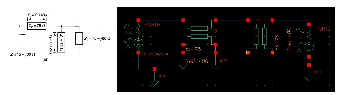
I want to know whether the way I have connected the Tline is correct for the stub and why I didn't get 15+j30 ohm.
Your connection is completely wrong as open stub.
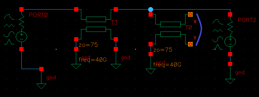
I see. This time I got 15.22+j30.48. I realized that I made a mistake short stub also. For example, If it is a short stub, I should connect X and Y (In the figure) correct?
Still completely wrong.
Surely consider relation between TLIN and TLIN4 of ADSsim.
No.
Before considering short stub, surely understand correct connection as open stub.
I know I didn't get exact 15+j30 ohm but I am still wondering what changes I need to make in connections to have correct open stub
To be frank, I don't even know why there are TLIN and TLIN4 and their purposes. I could only find this information http://edadocs.software.keysight.com...ine+Components
TLIN is only for single-ended.
TLIN4 can be used for both single-ended and differential.
Surely see and understand equation of ?spectre -h tline?.
transmission Confused ADS 相关文章: