关于cc2650 lanchpad pwmled的疑问
后来发现直接PWMLed线程中的PWM_open(Board_PWM1, ¶ms);就行了。
看来确实是PWM输出,既然如此,为何TI 还有些GPIO呢?
跟踪一下这个函数你就懂了
PWM_Handle PWMTimerCC26XX_open(PWM_Handle handle, PWM_Params *params)
{
PWMTimerCC26XX_HwAttrs *hwAttrs = handle->hwAttrs;
PWMTimerCC26XX_Object *object = handle->object;
/* Check if PWM already open */
uint32_t key = Hwi_disable();
if (object->isOpen)
{
Hwi_restore(key);
Log_error1("PWM_open(%x): Unit already in use.", (UArg) handle);
return NULL;
}
object->isOpen = 1;
Hwi_restore(key);
/* Open timer resource */
GPTimerCC26XX_Params timerParams;
GPTimerCC26XX_Params_init(&timerParams);
timerParams.width = GPT_CONFIG_16BIT;
timerParams.mode = GPT_MODE_PWM;
timerParams.debugStallMode = GPTimerCC26XX_DEBUG_STALL_OFF;
GPTimerCC26XX_Handle hTimer = GPTimerCC26XX_open(hwAttrs->gpTimerUnit, &timerParams);
/* Fail if cannot open timer */
if (hTimer == NULL)
{
Log_error2("PWM_open(%x): Timer unit (%d) already in use.", (UArg) handle, hwAttrs->gpTimerUnit);
object->isOpen = false;
return NULL;
}
/* Open pin resource */
PIN_Config pinConfig;
/* Initial open of pin handle with no pins in it. Should never fail. */
if (hPins == NULL)
{
pinConfig = PIN_TERMINATE;
hPins = PIN_open(&pinState, &pinConfig);
}
/* Invert PWM idle level since pin output is inverted */
uint32_t idleLevel = PIN_GPIO_HIGH;
if (params->idleLevel == PWM_IDLE_HIGH)
{
idleLevel = PIN_GPIO_LOW;
}
/* Generate pin config for PWM pin.
* Output is inverted to make PWM duty calculations independent of period
*/
pinConfig = hwAttrs->pwmPin | PIN_INPUT_DIS | PIN_GPIO_OUTPUT_EN | idleLevel |
PIN_INV_INOUT | PIN_PUSHPULL | PIN_DRVSTR_MAX;
/* Fail if cannot add pin */
if (PIN_add(hPins, pinConfig) != PIN_SUCCESS)
{
Log_error2("PWM_open(%x): PIN (%d) already in use.", (UArg) handle, hwAttrs->pwmPin);
GPTimerCC26XX_close(hTimer);
object->isOpen = false;
return NULL;
}
/* Store configuration to object */
object->periodUnit = params->periodUnits;
object->periodValue = params->periodValue;
object->dutyUnit = params->dutyUnits;
object->dutyValue = params->dutyValue;
object->idleLevel = params->idleLevel;
object->hTimer = hTimer;
/* Configure PWM period*/
uint32_t period = object->periodValue;
if (PWMTimerCC26XX_setPeriod(handle, period) != PWM_STATUS_SUCCESS)
{
Log_error1("PWM_open(%x): Failed setting period", (UArg) handle);
PIN_remove(hPins, hwAttrs->pwmPin);
GPTimerCC26XX_close(hTimer);
object->isOpen = false;
return NULL;
}
/* Corner case: If using duty unit PWM_DUTY_FRACTION or PWM_DUTY_US with
value 0, then duty is already set by setPeriod. Skip if so. */
PWM_Duty_Units unit = object->dutyUnit;
uint32_t value = object->dutyValue;
if (!(unit == PWM_DUTY_FRACTION || (value == 0 && unit == PWM_DUTY_US)))
{
if (PWMTimerCC26XX_setDuty(handle, value) != PWM_STATUS_SUCCESS)
{
Log_error1("PWM_open(%x): Failed setting duty cycle", (UArg) handle);
PIN_remove(hPins, hwAttrs->pwmPin);
GPTimerCC26XX_close(hTimer);
object->isOpen = false;
return NULL;
}
}
Log_info1("PWM_open(%x): Opened with great success!", (UArg) handle);
return handle;
}
感谢你的回复,我刚开始用这片板子和CCS 工具,我只有在github上才看到你贴的这个程序 https://github.com/energia/emt/b ... LE/PWMTimerCC26xx.c
而我在TI上只有看到一些headfiles.具体在http://software-dl.ti.com/dsps/d ... gen/html/index.html
我想知道我应该从哪里打开你提到的源文件。因为后面的学习还将用到。
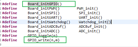
另外我在追踪代码的时候发现我前面提到过的GPIO_write(n,m)只是个定义。具体见图片。
 。整个学习资源怎么使用还望指点
关于上面问题,自己回答一下,供其他小伙伴查找:
PWM的源文件在 C:\ti\tirtos_cc13xx_cc26xx_2_20_01_08\products\tidrivers_cc13xx_cc26xx_2_20_01_10\packages\ti\drivers\pwm
