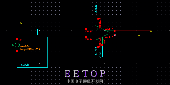
关于veriloga写出来的全差分运放问题
`include "discipline.h"
`include "constants.h"
// $Date: 1997/08/28 05:45:21 $
// $Revision: 1.1 $
//
//
// Based on the OVI Verilog-A Language Reference Manual, version 1.0 1996
//
//
`define PI3.14159265358979323846264338327950288419716939937511
//--------------------
// opamp-diff
//
// - differential operational amplifier
//
// vin_p,vin_n: differential input voltage [V,A]
// vout_p,vout_n:differential output voltage [V,A]
// vref: reference voltage [V,A]
// vspply_p: positive supply voltage [V,A]
// vspply_n: negative supply voltage [V,A]
//
// INSTANCE parameters
//gain= gain []
//freq_unitygain = unity gain frequency [Hz]
//rin= input resistance [Ohms]
//vin_offset= input offset voltage referred to negative [V]
//ibias= input current [A]
//iin_max= maximum current [A]
//slew_rate= slew rate [A/F]
//rout= output resistance [Ohms]
//vsoft= soft output limiting value [V]
//
// MODEL parameters
//{none}
//
module opamp_diff(vref, vin_p, vin_n, vspply_p, vspply_n, vout_p, vout_n);
input vref, vspply_p, vspply_n;
inout vout_p, vout_n, vin_p, vin_n;
electrical vout_n, vout_p, vref, vin_p, vin_n, vspply_p, vspply_n;
parameter real gain = 835e3;
parameter real freq_unitygain= 1.0e6;
parameter real rin = 1e6;
parameter real vin_offset = 0.0;
parameter real ibias = 0.0;
parameter real iin_max = 100e-6;
parameter real slew_rate = 0.5e6;
parameter real rout = 80;
parameter real vsoft = 0.5;
real c1;
real gm_nom;
real r1;
real vmax_in;
real vin_val;
electrical cout_p, cout_n;
analog begin
@ ( initial_step or initial_step("dc") ) begin
c1 = iin_max/(slew_rate);
gm_nom = 2 * `PI * freq_unitygain * c1;
r1 = gain/gm_nom;
vmax_in = iin_max/gm_nom;
end
vin_val = V(vin_p,vin_n)/2 + vin_offset;
//
// Input stage.
//
I(vin_p, vin_n) <+ (V(vin_p, vin_n) + vin_offset)/ rin;
I(vref, vin_p) <+ ibias;
I(vref, vin_n) <+ ibias;
//
// GM stage with slewing
//
I(vref, cout_p) <+ V(vref, cout_p)/100e6;
I(vref, cout_n) <+ V(vref, cout_n)/100e6;
if (vin_val > vmax_in) begin
I(vref, cout_p) <+ iin_max;
I(vref, cout_n) <+ -iin_max;
end
else if (vin_val < -vmax_in) begin
I(vref, cout_p) <+ -iin_max;
I(vref, cout_n) <+ iin_max;
end
else begin
I(vref, cout_p) <+ 1*gm_nom*vin_val ;
I(vref, cout_n) <+ -1*gm_nom*vin_val ;
end
//
// Dominant Pole.
//
I(cout_p, vref) <+ ddt(c1*V(cout_p, vref));
I(cout_p, vref) <+ V(cout_p, vref)/r1;
I(cout_n, vref) <+ ddt(c1*V(cout_n, vref));
I(cout_n, vref) <+ V(cout_n, vref)/r1;
//
// Output Stage.
//
I(vref, vout_p) <+ V(cout_p, vref)/rout;
I(vout_p, vref) <+ V(vout_p, vref)/rout;
I(vref, vout_n) <+ V(cout_n, vref)/rout;
I(vout_n, vref) <+ V(vout_n, vref)/rout;
//
// Soft Output Limiting.
//
if (V(vout_p) > (V(vspply_p) - vsoft))
I(cout_p, vref) <+ gm_nom*(V(vout_p, vspply_p)+vsoft);
else if (V(vout_p) < (V(vspply_n) + vsoft))
I(cout_p, vref) <+ gm_nom*(V(vout_p, vspply_n)-vsoft);
if (V(vout_n) > (V(vspply_p) - vsoft))
I(cout_n, vref) <+ gm_nom*(V(vout_n, vspply_p)+vsoft);
else if (V(vout_n) < (V(vspply_n) + vsoft))
I(cout_n, vref) <+ gm_nom*(V(vout_n, vspply_n)-vsoft);
end
endmodule
求前辈帮忙
vin_offset设的多少?
这不是挺好么,你想要什么?
Use book about VHDL Coding.
google find
http://www.designers-guide.org/Forum/YaBB.pl?num=1369925274
// model opamp -Non Ideal OpAmp Model
module opamp (voutp,voutn, vin_p, vin_n, vspply_p, vspply_n, vcm);
inputvin_p , vin_n , vcm;
inoutvspply_p, vspply_n;
output voutp,voutn ;
electrical vin_p, vin_n, voutp, voutn, vspply_p, vspply_n, vcm;
parameter realgain = 1412.5 exclude 0.0;
parameter realpole_freq = 172k;
parameter realrin = 12.0M exclude 0.0;
parameter realrout = 75.0;
parameter realibias = 0.0n;
parameter realvin_offset = 0.0u;
//parameter realslewp = 20.0M from (0:inf);
//parameter realslewn = -20.0M from (-inf:0);
real c1, r1;
real r_rout,gm_nom, vin_val;
electrical coutp, coutn, vref;
analog
begin
@(initial_step)// or initial_step("dc", "ac", "tran", "xf"))
begin
gm_nom = 1.0;
r1 = gain/gm_nom;
c1 = gm_nom/(`M_TWO_PI * pole_freq * gain);
r_rout = rout;
end
vin_val=V(vin_p, vin_n) + vin_offset;
// ------ Vrefis at Virtual Ground
V(vref,vspply_n) <+ 0.5*V(vspply_p,vspply_n);
// ------ Input Stage
I(vin_p, vin_n) <+ vin_val / rin;
I(vref, vin_p)<+ ibias;
I(vref, vin_n)<+ ibias;
// ------ GM stage
I(vcm, coutp) <+ (gm_nom/2)*vin_val ;
I(vcm, coutn) <+ -(gm_nom/2)*vin_val ;
// ------ Dominant Pole.
I(coutp, vcm) <+c1*ddt(V(coutp, vcm));
I(coutp, vcm) <+ V(coutp, vcm)/r1;
I(coutn,vcm) <+ c1*ddt(V(coutn, vcm));
I(coutn, vcm) <+ V(coutn, vcm)/r1;
// ------ Output Stage.
I(vcm, voutp) <+ (V(coutp) - (vcm))/r_rout;
I(voutp, vcm) <+ V(voutp, vcm)/r_rout;
I(vcm, voutn) <+ (V(coutn) - V(vcm))/r_rout;
I(voutn, vcm) <+ V(voutn, vcm)/r_rout;
end
endmodule
vin——offset设的是0
估计你输入V6的DC offset不为零
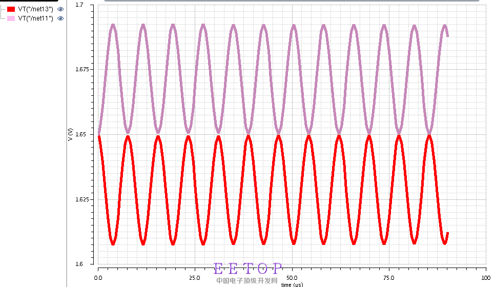
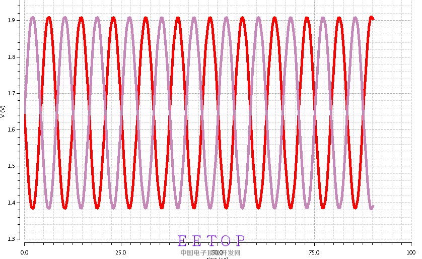
你这是一种差分,Verilog Code的也是一种差分。差分输出的本质是啥?
两个输出端之和是0,输出端之差是输入端的放大倍数。
要改成你想的那样,你要想好是为啥?