SDM 加Dither求教
clear
fs=26e6;% sample clock
NumberSamples=2^12;
BusSize=28; %bits
Fraction=0.61; % usable 0 to 1
FractionInternal=2^BusSize*Fraction;
AccumulatorBits=28 ; %bits
AccumulatorSize=2^AccumulatorBits;
% adither=2^3/(2^AccumulatorBits);
% dither_array=FractionInternal*adither*randn(1,NumberSamples);
dither_array=zeros(1,NumberSamples);
C1(1:NumberSamples)=0;%Carry out of the first accumulator
C2(1:NumberSamples)=0;%Carry out of the 2nd accumulator
C3(1:NumberSamples)=0;%Carry out of the 3rd accumulator
U1(1:NumberSamples)=0;%output of the 1st accum
U2(1:NumberSamples)=0;%output of the 2nd accum
U3(1:NumberSamples)=0;%output of the 3rd accum
for index=2:NumberSamples
U1(index)=FractionInternal+dither_array(index)+U1(index-1);% adder model
U2(index)=U1(index-1)+U2(index-1);
U3(index)=U2(index-1)+U3(index-1);
if U1(index)>AccumulatorSize
C1(index)=1;
U1(index)=U1(index)-AccumulatorSize;
end
if U2(index)>AccumulatorSize
C2(index)=1;
U2(index)=U2(index)-AccumulatorSize;
end
if U3(index)>AccumulatorSize
C3(index)=1;
U3(index)=U3(index)-AccumulatorSize;
end
Y1(index)=C2(index)+C3(index)-C3(index-1);% feedback from the 2nd & 3rd stage
Yout(index)=C1(index)+Y1(index)-Y1(index-1);% output to the divider
end
MeanFrac=mean(Yout);
fprintf('\nMeanFracMASH= %1.4f\n',MeanFrac);
x_legend=fs/NumberSamples*linspace(0,NumberSamples-1,NumberSamples);
Yout_sp=20*log10(abs(fft(Yout)));
% plot(20*log10(abs(fft(Yout))));
semilogx(x_legend(1:NumberSamples/2),Yout_sp(1:NumberSamples/2),'b');
呵呵,你把你的输入写成0.5,不加dither试试咯!
非常感谢fuyibin的指教,之前也考虑在特殊情况下看看,可惜没搞清楚fractional spur在哪?
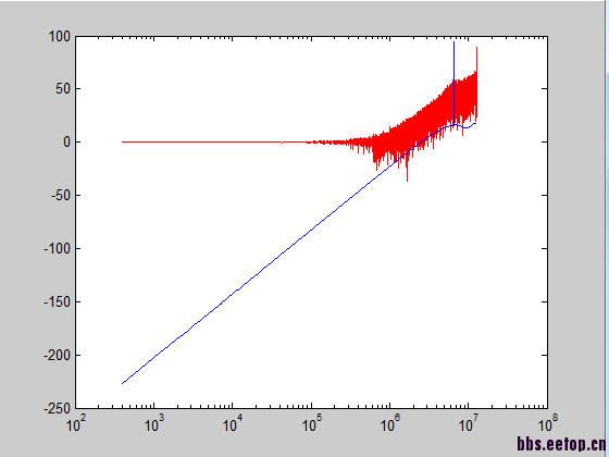
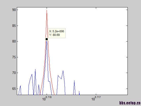
上图是输入0.5时,红色为在LSB上加dither,蓝色为在MSB上加dither
从这个图可以看出来如果在MSB上加dither的话fractional spur确实被打散了,通过时域看就更明显了,但是对应的是噪底抬升,这也是合理的。
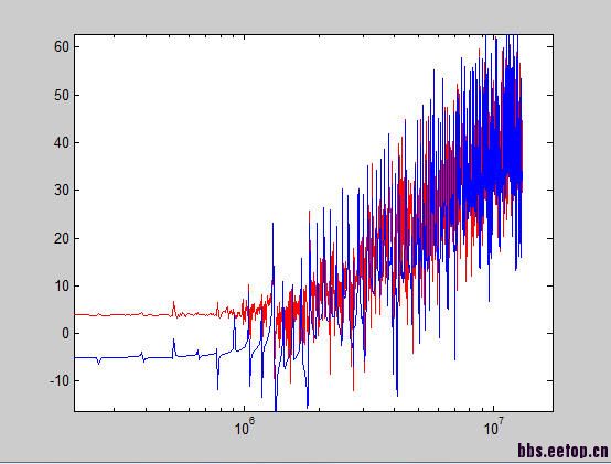
上图是输入0.6时分别在MSB和LSB上加dither的结果
但是发现在MSB上并不能完全消掉fractional spur。
所以我的问题是:
1. 在LSB上加dither只能减小fractional spur,我们一般是在低LSB上加是否够用呢,比如在fractional pll里?
2. 0.6输入下MSB也不能完全消除,是否意味着对于任意输入而言,spur不能完全消除,只能减小,(0.5较为特殊)?还是说输入信号随机性不够亦或数据点数不足所致?
还请多多指教
看不到你发的图片,不过也可以猜到是什么
其实加dither是为了打断某些输入pattern在DSM 里的循环
由于对于数字设计是2进制的运算,在0.5,0.25,0.75,0.125,0.375,0.625等等输入上
二进制运算是由固定循环的,就是输出分频系数周期性的循环,0.5循环最短,可能每4个就循环一次0
会有很多这样输入值会让输出循环
如果输出pattern是循环的,那么就说明能量集中在某几个频点,就是spur
dither加入就是为了打断这些循环,其实只要加在最低位1bit就可以了,比如20bit的最低位
这一位的dither会累积在DSM的积分器,影响整数位的进位
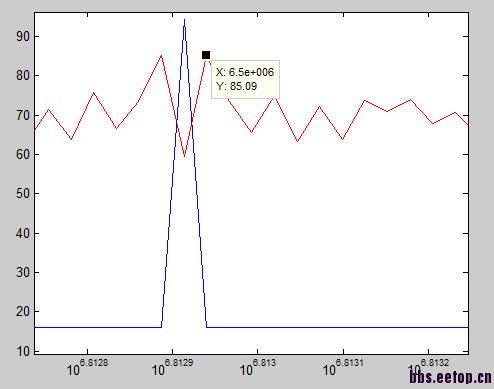
0.5输入
0.5输入局部放大
再次感谢,不好意思上图不是很熟,那为什么我加了8bit的 dither,0.6的spur只是减小而没有完全消失,这个正常么?
0.6输入
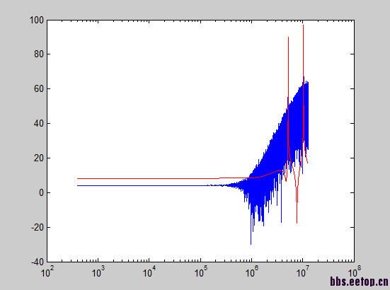
0.6输入局部放大
不会消失的,只会回到附近的平均值上,我认为目前的结果是正确的
谢谢热情回答,, 只不过好像我这里只在LSB上加有点困难,较周围的噪底还是高不少!
还有个方法就是看看不同的initial state。
顺便mark下,回头看
你好,我想请教你几个SDM PLL的问题。
说
默默地看着上面两楼,我觉得我们中华不愧是礼仪之邦,13楼谦虚有礼,14楼乐于助人,满满都是正能量~