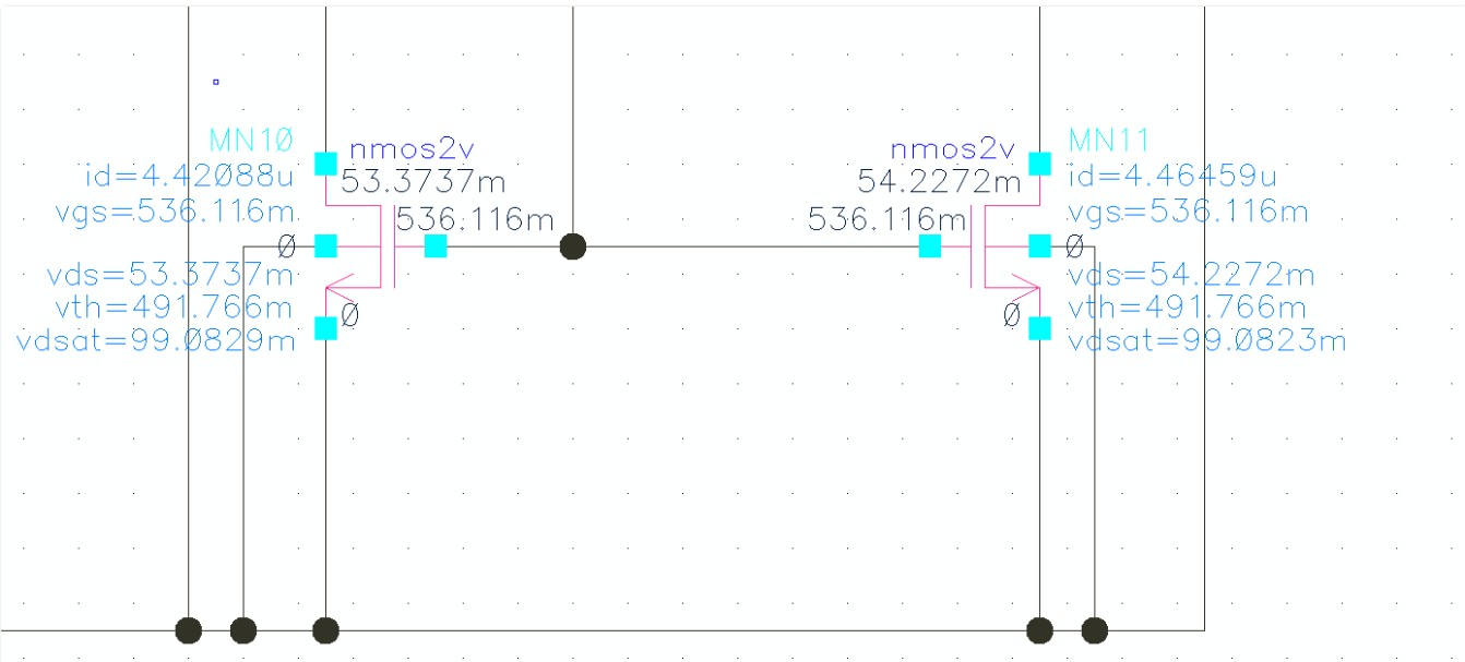
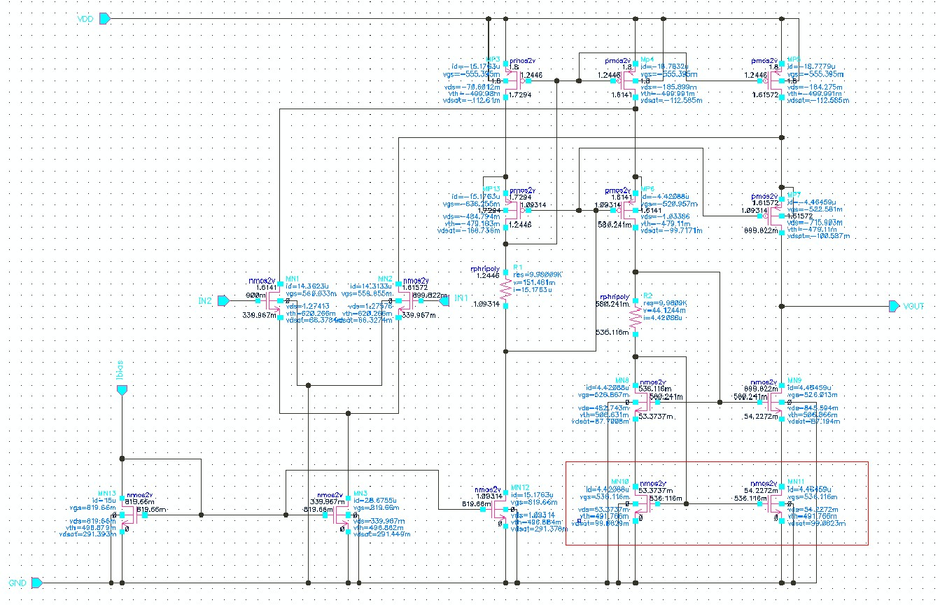
设计的折叠共源共栅vds>vgs-vth却是线性区,vds<vdsat


能不能上传小一点的图片啊!请注意
一个图片4、5M,上传时也能看出来啊!
要知道1920*1080的照片常见的jpg大小也就300k-500k之间
你能解决问题吗?
vgs-vth is too small
饱和区 vds>vdsat
请先解决方便多有数人看的问题
问题就两个 1.过驱动电压留的太少
2.W/L设置和Ibias不合理,只要较少的过驱动电压 电路也能工作起来,电路工作在弱开启区
我减小W/L还是出现一样的情况啊,按理来说I不变减小W/L,Vov增大啊,Vov是增大了,但还是始终Vds<Vdsat,或者改变尾电流,增大共源共栅的电流,最后两个管子也是线性区,并且我的增益远远下降
先帮大家把他的图缩小


细看了一下,问题太多
整个bias都是乱的,voltage,current全都乱的
另外我个人是非常讨厌这种对cascode进行偏置的方式,非常不稳
做电路之前,先算清楚,不要搞try-and-simulation把电阻R2调大即可,大约20K~30K之间
我也没用过电阻给cascod管子做偏置,这种一是,使电路不match,二是电阻的阻值在加工过程中非常的不准吧,这样偏置就会偏很多,很容易使电路不正常工作。
经常在坛子里看到您老人家,看到你的签名,想问你个问题,在cmos image sensor中,用于校准的PGA ,为什么要用switch capacitor 用于调节增益呢? 为什么不用电阻? 我想是不是因为pixel信号是非连续的,还有运放的负载希望看到的是容性负载而不会影响增益呢?
还有一点就是,如果我增益变大了,那么整个闭环带宽减小,这样速度也就小了,请问如果我50MHz的系统工作时钟,那么20ns的时间就要采样并且稳定在一定精度之内吗?还是有其他考虑? 速度是如何做上去的呢?
问题好多,希望您能抽时间看一下。
谢谢!你电路问题太多了,或者说你这电路只适合仿真用,没啥实际用途,这样的电路你做多少都没用的!这个电路你加大电阻看看,但是在电路结构,器件参数选取都不正常,你在这个电路上花大精力,还不如再找一个电路结构!
这种结构不是不能用,如果设置偏置电压的基础不老牢固的话,还是先从最基础的开始
可是我是算好的啊,就是因为算出来和仿真出来的东西差距太大,我才调试的嘛,我按照Alen的书P247的设计流程来的,我的功耗要求是<0.16mW,我的电流分配就会受到限制,是不是我的MP4、MP5管子的电流小了,导致我的cascode始终工作在线性区,我还是刚入门呢,很多不懂,请大神指点
First of all,I highly suggest you to make the current flowing through the input stage and the cascode stage be equal.Secondly, I don't know your requirements for DC gain? your load? your bandwidth? etc.
Thirdly, do not use this way to bias the cascode. It's ok, but better not.
Last, it's better that you can give us the sizes of your transistors if those are not confidential.Well, some information is confidential to me.
ok, the basic idea is that PGA can be used not only for calibration the amplitude of your signal, it can be used for other purpose.
for calibration, the question is that why do you think using resistors is better ? matching, noise, linearity, etc. Think about that !
In addition, we normally use OTA, not op amp, how large the resistor should be ?
Gain error, linearity, noise, all of them should be considered !
How to increase the speed ? Simplest way is to increase power consumption. Circuit techniques to increase speed are confidential.50MHz is fast for image sensor, but it also depends on your resolution and pixel size.for example, 4k*4k and pixel size is larger than 6um, it's fast.
like 1.5um pixel size, it's ok.Thanks for your reply. I will think more for circuit design.
Actually,I don't know why shouldn't use the bias of the cascode,because of the resistance?if i put the mosfet instead of resistance?andcan you give me some better solution of bias circuit. ijust imitate the book of Alen.As I said, it's ok, but better not use it. Apparently, it's because of the resistor. matching, area, swing....many problems. if you do layout, you will find out that adding a resistor there looks very strange.I didn't insist you to give up using this bias circuit, actually you can. I just don't like it according to my experiences.
Sorry, I can give you some advice, point out the problems you may have, but I won't give you solutions directly.OK ,I just try change the bias circuit
有些乱阿....VDS>VDSAT ,,,保和。
