TPS63061使用问题
TPS63061在瞬态加重负载情况下,电压会下跌,这是它固有特性吗?有什么措施能避免电压下跌?
Hi
你的输出电容多大,很可能是你的输出电容偏小。
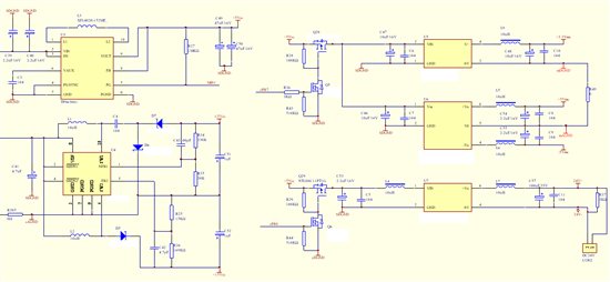
最好是能提供电路图。
加载瞬间电压肯定会下跌,下跌后如果电压再恢复,关注动态的超调量和恢复时间以及负载的调整率是否在指标范围内;如果不恢复,直接跌保护了,那要考虑环路的动态响应。
下跌后能恢复,但造成后续电源模块重新启动
没有太好的解决办法,可以尝试适当增加输出电容。或者考虑给负载跳变大的一路单独供电。
根据datasheet P21 输入电容和输出电容的说明再改进测试一下。
"
Input Capacitor
Atleast a20μFinput capacitoris recommended to improve transient behaviorofthe regulator andEMIbehavior
ofthe total powersupplycircuit.Aceramiccapacitorplacedascloseaspossibleto the VINandPGNDpinsof
the IC is recommended.
OutputCapacitor
Forthe outputcapacitor,useofasmallceramiccapacitorsplacedascloseaspossibleto the VOUTandPGND
pinsofthe IC is recommended. If, for anyreason, the applicationrequires the useoflarge capacitorswhichcan
not beplacedclose to the IC, useasmaller ceramiccapacitor in parallelto the large capacitor. Thesmall
capacitor shouldbeplacedascloseaspossibleto the VOUTandPGNDpinsofthe IC. Therecommended
typical outputcapacitorvalueis 66µFwithavarianceasoutlinedin Table2.
Thereis alsonoupperlimit for the outputcapacitancevalue.Largercapacitorswillcauselower outputvoltage
ripple aswellaslower outputvoltagedropduringload transients.
Whenchoosing input and output capacitors, it needs to be kept in mind,that the value of capacitance
experiencessignificantlosses from their rated valuedependingonthe operatingtemperature andthe operating
DCvoltage.It's notuncommonfor asmallsurfacemountceramiccapacitorto lose 50%andmoreofit's rated
capacitance. Forthis reason, it is important to usealarger value ofcapacitance or acapacitor withhigher
voltageratingin orderto ensurethe required capacitanceatthe full operatingvoltage.
"
Hi
有的话将电感改为1uF(饱和电流够), 动态性能略好一点。
另外您的输入电容没有完全画出来,建议超过100uF, 多个并连,减小ESR. 输出电容可以在增加一个47uF低ESR电容。
在这个设计中,如果你的TPS63061采用了升降压的架构,那么考虑到升压,实际上你的最大负载应小于1A, 在你的后续几路启动上,如果没有要求同时启动,尽量采取一些延时,可以使得逐步启动,减小负载的动态变化,输出电压的波动就会降低。(在datasheet上,即便Vin=8V时,负载从600mA跳到1A, 负载电压的波动大约在150mV)
后续电源模块的功率估计太大,由于模块是开关电源,导致在启动瞬间将有近2倍于模块功率的瞬时功耗,其中,24V输出模块额定功率是2W,按照2倍计算,瞬时电流是太大了,不知TI有没有更大输出电流的类似芯片可供选择
Hi
你的升降压模块的输入电压范围是多大?(提供5V的)
对于后面模块的瞬间启动电流,建议采用限制,例如增加softstart时间等。
输入电压一种是单节锂电池,另一种是4节5号电池
Hi
在TI的同类芯片中有TPS63020/1的输出电流可以比TPS63061高,它的switcher电流3.5A比TPS63061 2A高,但是它的输入电压是1.8~5.5V, 无法完全兼容您的两种电源供应(使用于锂电池和3节5号电池)。 它的动态特性从示意图上看: VIN = 4.2 V, IOUT = 500 mA to 1500 mA,输出电压变化是100mV, 比TPS63061好。
Hi
如果选用TPS63020, 就变成只能升压。
如果可以选择外部MOS的设计,或许您可以选择TPS43000: http://www.ti.com.cn/product/cn/tps43000
TPS4300能实现BUCK-BOOST 无缝切换吗
Hi
采用SEPIC converter(或者flyback)的架构,见datasheet: http://www.ti.com.cn/general/cn/docs/lit/getliterature.tsp?genericPartNumber=tps43000&fileType=pdf 第二十二页。
Hi
可以做到输出升降压无切缝转换。