AIC 3204的配置问题——"ADC和DAC模块同时工作"
时间:10-02
整理:3721RD
点击:
ti的工程师:
我这里有一个工程,同时要使能AIC3204的ADC和DAC,IIS总线接的是6748,这里双向通信我们之前检测是没有问题的。AIC3204电路如下
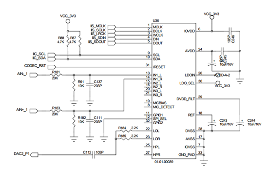
我们目前数字信号从DIN输入后,LOL和LOR有模拟信号输出。AIN-1、AIN+1模拟信号输入,但是DOUT数字信号一直没反应。我改了好几遍偏置一直没啥反应请ti的工程师看看是不是哪里配置的有问题。
void aic3204Init(void)
{
		CODEC_RESET = 1;
		delay_ms(2);
		CODEC_RESET = 0;

		//;p Reset 1     # Release the reset pin
		//;# RESET
		aic3204_res = aic3204_Write_Reg(0x00,0X0);		//WW 30, 00h, 00h   ; # Select register page 0
		aic3204_res = aic3204_Write_Reg(0x01,0X1);		//WW 30, 01h, 01h   ; # I2C reset

		delay_ms(10);

		//;# CLOCK SETTINGS
		aic3204_res = aic3204_Write_Reg(0x0B,0X81);		//WW 30, 0Bh, 81h   ; # PoWWer up the NDAC divider WWith value 1
		aic3204_res = aic3204_Write_Reg(0x0C,0X82);		//WW 30, 0Ch, 82h   ; # PoWWer up the MDAC divider WWith value 2
		aic3204_res = aic3204_Write_Reg(0x0D,0X00);		//WW 30, 0Dh, 00h   ; # Program OSR for DAC to 128 (MSB)
		aic3204_res = aic3204_Write_Reg(0x0E,0X80);		//WW 30, 0Eh, 80h   ; # Program OSR for DAC to 128 (LSB)
		//12 13 14
		//w 30 12h 81    # Power up the NADC divider with value 1
		//w 30 13h 82    # Power up the MADC divider with value 2
		//w 30 14h 80    # Program OSR for ADC to 128
		aic3204_res = aic3204_Write_Reg(0x12,0X81);
		aic3204_res = aic3204_Write_Reg(0x13,0X82);
		aic3204_res = aic3204_Write_Reg(0x14,0X80);
		//;# DIGITAL INTERFACE
		aic3204_res = aic3204_Write_Reg(0x1B,0X00);		//WW 30, 1Bh, 00h   ; # I2S, 16-bit, BCLK and WWCLK are inputs
		//;# PROCESSING BLOCK USAGE
		aic3204_res = aic3204_Write_Reg(0x3C,0X08);		//WW 30, 3Ch, 08h   ; # Select DAC processing block PRB_P8
		//w 30 3D 04    # Select ADC processing block PRB_R4
		aic3204_res = aic3204_Write_Reg(0x3D,0X04);
		//;# ANALOG POWWER SUPPLY
		aic3204_res = aic3204_Write_Reg(0x00,0X01);		//WW 30, 00h, 01h   ; # Select register page 1
		aic3204_res = aic3204_Write_Reg(0x01,0X08);		//WW 30, 01h, 08h   ; # Disable internal crude AVDD before poWWering up the internal AVDD LDO
		aic3204_res = aic3204_Write_Reg(0x02,0X01);		//WW 30, 02h, 01h   ; # Enable internal analog LDO, analog blocks poWWered																				//;WW 30, 02h, 00h   ; # Enable internal analog LDO, analog blocks poWWered
		aic3204_res = aic3204_Write_Reg(0x0A,0X40);		//WW 30, 0Ah, 40h   ; # Common mode set to 0.75V
		//;# MICPGA DELAY, REFERENCE CHARGING AND HEADPHONE DE-POP
		//;WW 30, 47h, 31h   ; # MICPGA startup delay is 3 ms
		aic3204_res = aic3204_Write_Reg(0x7B,0X01);		//WW 30, 7Bh, 01H   ; # Reference charging time is 40 ms
		//aic3204_res = aic3204_Write_Reg(0x14,0X65);		//;WW 30, 14h, 65h   ; # HP driver poWWer-up: 50 ms soft routing step time, 5.0 time constants, 6k resistance
		//;# AUDIO ROUTING
		//aic3204_res = aic3204_Write_Reg(0x0C,0X08);		//;WW 30, 0Ch, 08h   ; # HPL routing: Left channel
		//aic3204_res = aic3204_Write_Reg(0x0D,0X08);		//;WW 30, 0Dh, 08h   ; # HPR routing: Right channel
		aic3204_res = aic3204_Write_Reg(0x0E,0X08);		//WW 30, 0Eh, 08h   ; # LOL routing: Left channel
		aic3204_res = aic3204_Write_Reg(0x0F,0X08);		//WW 30, 0Fh, 08h   ; # LOR routing: Right channel

		//Full-Differential Mono Mic connected to IN1L/IN1R  select page 1
		//w 30 34 00    # No routed to Left MICPGA Positive
		//w 30 36 00    # No routed to Left MICPGA Negative
		//w 30 37 40    # IN1R is routed to Right MICPGA Positive with 10K resistance
		//w 30 39 10    # IN1L is routed to Right MICPGA Negative with 10K resistance

		aic3204_res = aic3204_Write_Reg(0x34,0X00);
		aic3204_res = aic3204_Write_Reg(0x36,0X00);
		aic3204_res = aic3204_Write_Reg(0x37,0X40);
		aic3204_res = aic3204_Write_Reg(0x39,0X10);


		aic3204_res = aic3204_Write_Reg(0x12,0X00);		//WW 30, 12h, 00h   ; # LOL driver is not muted
		aic3204_res = aic3204_Write_Reg(0x13,0X00);		//WW 30, 13h, 00h   ; # LOR driver is not muted
		aic3204_res = aic3204_Write_Reg(0x09,0X3C);		//WW 30, 09h, 3Ch   ; # Output Driver Power Control ALLOUT powered up

		delay_ms(10);
		//mov A,28h     ;after 18 cmds do delay 8.6ms
		//call dly_lcd_timex
		aic3204_res = aic3204_Write_Reg(0x00,0X00);		//WW 30, 00h, 00h   ; # Select register page 0
		aic3204_res = aic3204_Write_Reg(0x3F,0X0D6);	//WW 30, 3Fh, 0D6h   ; #
		aic3204_res = aic3204_Write_Reg(0x40,0X00);		//WW 30, 40h, 00h   ; #

}
上面描述说反了,DAC模块有输出而ADC模块没有输出。