CC1101信道串扰问题
各位大神,我在使用CC1101的时候,遇到如下问题,我购买的是模块,并非自己设计,所有参数,使用smart rf生成,参数如下:
base frequency=432.9999817mhz,data rate=38.3835kbaud,其他参数均根据smart rf生成,因为smart rf中的cc1101里expert mode没有433选择,所以使用了generic 868Mhz的参数,在generic 868Mhz里选择38.4,Optimized for sensitivity,然后base frequency改成432.9999817,Tx Power改成10,其他不改。
现在发现,信道串扰很严重:
40信道(carrier frequency=440.997864Mhz)会串扰0信道(432.9999817Mhz),
80信道(carrier frequency=448.995911)会串扰40信道(440.997864Mhz),
(但是80信道和0信道却不会串扰)。
104信道(carrier frequency=453.794739Mhz)会串扰64信道(carrier frequency=445.796692),
当然还有其他信道串扰情况,无法全部测试。
以上串扰现象均在channel spacing=199.951172KHz,RX filter BW=101.562500,如果我将Channel spacing更改为333.251953,则不会出现串扰现象,请大神帮助!感谢感谢!
你好 问题解决了吗 我也遇到类似问题
Long,
你把所有的配置都发上来吧,smartrf sdudio截图就好。
我看看你channel space deviation 等。
图片呢?我就看到了一个 点。
呵呵,谢谢啊,尽然还有人关注这个问题啊,图如下:
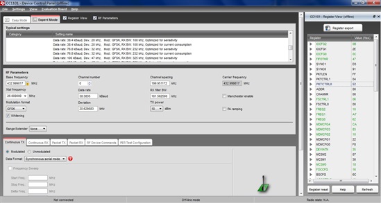
参数如下:
// Rf settings for CC1101
RF_SETTINGS code rfSettings = {
0x01, // IOCFG2 GDO2 Output Pin Configuration
0x2E, // IOCFG1 GDO1 Output Pin Configuration
0x0C, // IOCFG0 GDO0 Output Pin Configuration
0x44, // FIFOTHR RX FIFO and TX FIFO Thresholds
0xD3, // SYNC1 Sync Word, High Byte
0x91, // SYNC0 Sync Word, Low Byte
0xFF, // PKTLEN Packet Length
0x04, // PKTCTRL1 Packet Automation Control
0x52, // PKTCTRL0 Packet Automation Control
0x00, // ADDR Device Address
0x00, // CHANNR Channel Number
0x06, // FSCTRL1 Frequency Synthesizer Control
0x00, // FSCTRL0 Frequency Synthesizer Control
0x10, // FREQ2 Frequency Control Word, High Byte
0xA7, // FREQ1 Frequency Control Word, Middle Byte
0x62, // FREQ0 Frequency Control Word, Low Byte
0xCA, // MDMCFG4 Modem Configuration
0x83, // MDMCFG3 Modem Configuration
0x10, // MDMCFG2 Modem Configuration
0x22, // MDMCFG1 Modem Configuration
0xF8, // MDMCFG0 Modem Configuration
0x35, // DEVIATN Modem Deviation Setting
0x07, // MCSM2 Main Radio Control State Machine Configuration
0x30, // MCSM1 Main Radio Control State Machine Configuration
0x18, // MCSM0 Main Radio Control State Machine Configuration
0x16, // FOCCFG Frequency Offset Compensation Configuration
0x6C, // BSCFG Bit Synchronization Configuration
0x43, // AGCCTRL2 AGC Control
0x40, // AGCCTRL1 AGC Control
0x91, // AGCCTRL0 AGC Control
0x87, // WOREVT1 High Byte Event0 Timeout
0x6B, // WOREVT0 Low Byte Event0 Timeout
0xFB, // WORCTRL Wake On Radio Control
0x56, // FREND1 Front End RX Configuration
0x10, // FREND0 Front End TX Configuration
0xE9, // FSCAL3 Frequency Synthesizer Calibration
0x2A, // FSCAL2 Frequency Synthesizer Calibration
0x00, // FSCAL1 Frequency Synthesizer Calibration
0x1F, // FSCAL0 Frequency Synthesizer Calibration
0x41, // RCCTRL1 RC Oscillator Configuration
0x00, // RCCTRL0 RC Oscillator Configuration
0x59, // FSTEST Frequency Synthesizer Calibration Control
0x7F, // PTEST Production Test
0x3F, // AGCTEST AGC Test
0x81, // TEST2 Various Test Settings
0x35, // TEST1 Various Test Settings
0x09, // TEST0 Various Test Settings
0x00, // PARTNUM Chip ID
0x04, // VERSION Chip ID
0x00, // FREQEST Frequency Offset Estimate from Demodulator
0x00, // LQI Demodulator Estimate for Link Quality
0x00, // RSSI Received Signal Strength Indication
0x00, // MARCSTATE Main Radio Control State Machine State
0x00, // WORTIME1 High Byte of WOR Time
0x00, // WORTIME0 Low Byte of WOR Time
0x00, // PKTSTATUS Current GDOx Status and Packet Status
0x00, // VCO_VC_DAC Current Setting from PLL Calibration Module
0x00, // TXBYTES Underflow and Number of Bytes
0x00, // RXBYTES Overflow and Number of Bytes
0x00, // RCCTRL1_STATUS Last RC Oscillator Calibration Result
0x00, // RCCTRL0_STATUS Last RC Oscillator Calibration Result
};