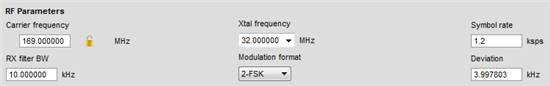
CC1120 channel filter bandwidth设置问题
根据TI设计笔记“CC11xx Sensitivity versus Frequency Offset and Crystal Accuracy”,接收滤波器带宽需满足如下条件:
BWchannel > BWsignal + 4 * XTALppm * fRF
对于2FSK/2GFSK调制,信号占用带宽(BWsignal)为:BWSignal = data rate + 2 * deviation
如,若data rate为2.4kbps,deviation为2.4kbps,XTALppm为10ppm,fRF为169MHz,则按照设计笔记公式计算:
BWchannel > 2.4k + 2.4k * 2 + 4 * 10ppm * 169MHz = 13.96kHz。
然而,在参考设计“ETSI Cat. 1 Receiver-Capable wM-Bus 169MHz RF Subsystem for Smart Gas and Water Meters”中,该设计的通讯参数包含了2.4kbps/169MHz/2GFSK, dev=2.4kHz,BOM单中采用的晶体误差如下,

在以上条件下,软件中设置的BWchannel却为7.8kHz(见代码preferredSettings2400设置)。
并在在key document中有如下描述:
CC1120 easily achieves and exceeds ETSI Category 2 receiver category compliance just using the
register settings, optimized for best RX sensitivity, found in the Smart RF7 Studio tool, where the receiver
bandwidth is set to 10 kHz (register CHAN BW = 0x14). This performance is sufficient to meet the wM-Bus
Nabcdefg modes' requirements, set in the EN13757-4:2013 document. 查阅SmartRF的设置如下:
这个设置亦不满足BWchannel > BWsignal + 4 * XTALppm * fRF的要求。
请问,以上参考设计,BWchannel设置是出于什么样的考虑?BWchannel > BWsignal + 4 * XTALppm * fRF 是否不一定需要满足,那这样的话BWchannel该如何设置?
liuzhe,
CC11xx Sensitivity versus Frequency Offset and Crystal Accuracy文档的理论是完全正确的。
但是你说的那个板子是老外做的,中国这边确实不太了解相关的考量。
你可以到TI E2E去问一下吗?https://e2e.ti.com/support/wireless_connectivity/f/155
谢谢理解。
好的,我已在TI E2E上询问。谢谢
https://e2e.ti.com/support/wireless_connectivity/f/156/t/447359
Hi Liuzhe,
I checked the topic, Good see you are closing to get the answer.:-).
是啊。以下是关键内容:
这种情况下2GFSK的信号带宽约为6.4kHz(用软件计算的,也可以按80%~90%乘以Carson's rule方法估算),考虑晶体误差后Signal BW + frequency error为13.2 kHz。
Setting FREQOFF_CFG to 0x30 enables feedback to PLL and increases BW from "programmed RX filter BW" to "programmed RX filter BW +/- RX filter BW/4".
Option 1: RX filter BW is programmed to 10 kHz, the feedback to PLL increases this filter to 15 kHz (although 10 kHz is still the noise BW). Appropriate for 13.2 kHz signal BW and frequency error
Option 2: RX filter BW is programmed to 7.8 kHz, the feedback to PLL increases this filter to 11.7 kHz (although 7.8 kHz is still the noise BW). Not appropriate for 13.2 kHz signal BW and frequency error
A programmed RX filter BW of 9 kHz and FB2PLL enabled seems to be the lower option in terms of RX filter BW
https://e2e.ti.com/support/wireless_connectivity/f/156/p/447359/1610555#1610555