改变CC2530的固件
The CC2530 Zigbee Network Processor is a special firmware image that gets loaded onto the CC2530. You may want to change the CC2530 firmware to use a different build. Changing the firmware on the CC2530 requires a CC-Debugger or SmartRF05EB. It is recommended to get the CC-Debugger since that includes a little adapter that you will need.
The ZNP Hex images are in the C:\Texas Instruments\CC2530ZNP_Mini_Kit_SW\bin folder after installation of the CC2530ZNP software package. Use the file CC2530-MK-Pro.hex.
Normally the MSP430 controls the CC2530 signals, but some of these signals are required to be controlled by the external programmer so we need to disconnect the MSP430 from the CC2530. Since the two are hardwired together we just configure all the shared signals to a tri-state configuration by setting them as inputs on the MSP430. There's a pre-made method and IAR project that does this.
In the HAL directory there's a IAR workspace named HAL Utilities. Open this workspace and click on the "Program ZNP" project to make it the active project. Click on Project : Download and Debug and then click Debug : Go to run the project. You should now see the red LED blinking quickly. This indicates that this program is running. This program is very simple; you'll notice that all it does is call setZnpInterfaceToInputs(). To see what this function does, double click on the function name (setZnpInterfaceToInputs) and in the right click menu select "Go to Definition of setZnpInterfaceToInputs". This will open the file hal_cc2530znp_target_board and you can see this function configures the ZNP interface signals (MRDY, SRDY, MOSI, MISO, SCLK, CS, RESET) as inputs. This is needed to allow an external programmer to control the 2530's Reset line.
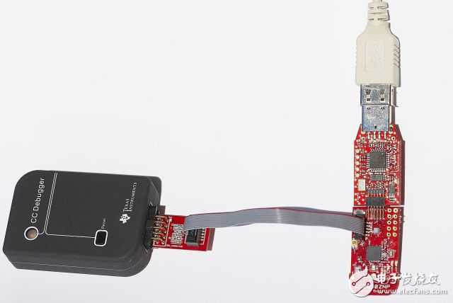
You'll also need an adapter to go from the 0.100" connector on the CC-Debugger (or SmartRF05EB) to the smaller 0.050" connector on the CC2530ZNP Target Board. This adapter is included with the CC-Debugger. Connect one end to the programmer and connect the other end to the CC2530ZNP target board. Be careful and be sure to line up pin 1 on the cable with pin 1 on the board. Pin 1 on the CC2530ZNP target board is the pin closest to the button - if you look closely you can see a little "1" silkscreened on the board.
Once you have the "Program ZNP" application running on the MSP430 (you should see the LED blinking furiously) then you can program the CC2530:
- Open the SmartRF Flash Programmer Application
- You should see a chip listed in the table (EB ID, Chip type, EB type, etc.). If you don't, press the Reset button on the CC-DEBUGGER. If you still don't see the chip listed then you have a problem.
- Press the "Read IEEE" button and verify that you are able to read the MAC address
- In the Flash Image text field, navigate to the CC2530 hex image you wish to load
- Select the "Erase, Program and verify" command
- Click the "Perform Actions" command
WARNING: do NOT select the "Read flash into hex file" option or else your existing hex file on disk will be erased without warning!
The CC2530 will now be programmed with the hex file. Disconnect the CC-Debugger and you may program the MSP430 with your application.
感谢小编分享~~~~~