C51跟atmega64的串行通信及PROTEUS仿真设计
51的UART所用的几个寄存器
SCON:SM0 SM1 SM2 REN RB8 TX8 RI TI
PCON: SMOD -- -- -- --- ---PD IDLE
T2CON: TF2 EXF2 RCLK TCLK EXEN2 TR2 C/_T CP/_RL2
TH2,TL2
波特率为9600bps
avr:atmega64的USART的两个
所用到的寄存器
这里用的是uart0,所以初始化时应该设置相关的寄存器有:
UCSR0A: RXC TXC UDRE FE DOR UPE U2X MPCM
UCSR0C :-- UMSEL UPM1 UPM0 USBS UCSZ1 UCSZ0 UCPOL
UBRR0H、UBRR0L、
UCSR0B :RXCIE TXCIE UDRIE RXEN TXEN UCSZ2 RXB8 TXB8
别问我这些都是代表什么含义,不懂自己翻书去。。
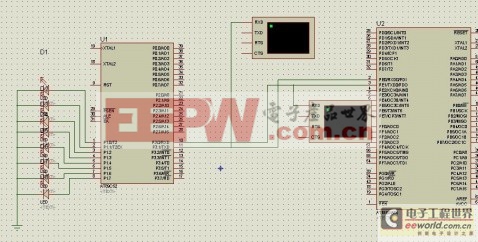
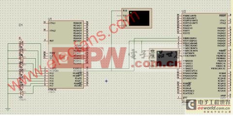
proteus仿真如下图:


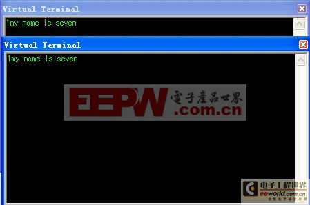
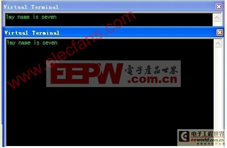
仿真结果如下图所示:


其中要注意的是:
因为我在仿真中只能选择atmega64的CKSEL Fuse中的8MHz,所以在AVR的程序中初始化波特率是按8MHz来计算的。所以仿真归仿真,注意实际中应用。
51单片机用定时器1来产生波特率时,看书据说模式2下,12MHz时最高只能到达4800bps。这里就只好用定时器2来。不过也挺好用的。。仿真时用的是8052核。。否则没反应不要怪我哦。。
最后把程序附上,里面有些变量声明了没有用到,当初只是实验。。
51的:
#include "reg52.h"
#define AA 0x61
#define commun_symbol 0x31
sbit LED=P2^0;
unsigned char Tx[]={"my name is seven!"};
void uart_init(void)
{
SCON = 0x50;
RCAP2H = 0xFF;
RCAP2L = 0xD9;
TH2 = 0xFF;
TL2 = 0xD9;
T2CON = 0x34;
}
void uart_send(unsigned char byData)
{
TI=0;
SBUF=byData;
while(TI==0);
TI=1;
}
unsigned char uart_receive(void)
{
RI=0;
while(RI==0);
RI=1;
return(SBUF);
}
void main()
{
unsigned char byBuff,i;
uart_init();
uart_send(commun_symbol);
while(1)
{
byBuff=uart_receive();
LED=1;
if(byBuff==0x31)
{
for(i=0;i20;i++)
{
P1=byBuff;
uart_send(Tx[i]);
}
}
}
}
atmega64的程序:
两个文件,一个是将函数模块化,别一个是主函数,调用(- -!最近习惯将程序模块化。。。)
//------------------uart.c---------------------
//----这里将通信函数模块化------------
#include iom64v.h>
void uart0_init(void)
{
UCSR0B = 0x00; //disable while setting baud rate
UCSR0A = 0x00;
UCSR0C = 0x06;
UBRR0L = 0x33; //set baud rate lo
UBRR0H = 0x00; //set baud rate hi
UCSR0B = 0x18;
}
void uart0_Transmit( unsigned char da
{
/* Wait for empty transmit buffer */
while ( !( UCSR0A (1UDRE0)) )
;
/* Copy ninth bit to TXB8 */
UCSR0B = ~(1TXB80);
//if ( da
//UCSR0B |= (1TXB80);
/* Put da
UDR0 = da
}
unsigned char uart0_Receive( void )
{
/* 等待接收数据*/
while ( !(UCSR0A (1RXC0)) )
;
/* 从缓冲器中获取并返回数据*/
return UDR0;
}
//--------------main.c-----------
//--------------------------------
#include iom64v.h>
#include "spi.h"
#define commun_symbol 0x31
//-----------send a commun_symbol-----
//-----------receive a commun_symbol--
// --no,continue receive||||||yes-->receive the da
void main()
{
unsigned char bybuff;
DDRB=0xff;
PORTB=0xff;
uart0_init();
{
do
{
bybuff=uart0_Receive();
}
while (bybuff!=commun_symbol);//commun_symbol);
while(1)
{
uart0_Transmit(bybuff);
bybuff=uart0_Receive();
PORTB=(0xff|bybuff);
}
}
}
- DSP 与PC 机串行通讯的设计(01-13)
- TMS320LF2407 DSP控制器的串行通信设计(01-26)
- TMS320C3x DSP和PC机的异步串行通信设计(03-02)
- DSP串行通信在减摇水舱试验台架控制系统中的应用(10-10)
- 高速DSP与串行A/D转换器TLC2558接口的设计(09-08)
- 基于FPGA的串行通信控制系统的设计(06-05)
