状态机“毛刺”的产生及消除方法程序
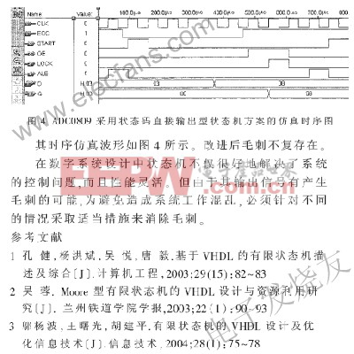
,即采用状态码直接输出型状态机,使状态和输出信号一致,使得输出译码电路被优化掉了,因此不会出现竞争冒险。这种方案,占用芯片资源少,信号与状态变化同步,因此速度快,是一种较优方案。但在设计过程中对状态编码时可能增加状态向量,出现多余状态。虽然可用CASE语句中WHENOTHERS来安排多余状态,但有时难以有效控制多余状态,运行时可能会出现难以预料的情况。因此它适用于状态机输出信号较少的场合。
若对ADC0809的采样控制采用状态码直接输出型状态机方案,其主要程序如下:
begin
lock=lock1;
process(current_state,eoc)
begin
case current_state IS
when st0 => next_state =st1;
when st1 => next_state =st2;
when st2 => next_state =st3;
when st3 => if (eoc =‘1’)then next_state =st3; else next_state =st4;end if;
when st4 => if (eoc =’0’)then next_state=st4;else next_state =st5; end if;
when st5 => next_state =st6;
when st6 => next_state =st0;
when others=> next_state =st0;
end case;
out4=current_state(5 downto 2);
ale=current_state(5); start =current_state(4);
oe=current_state(3); lock1=current_state(2);
end process;
process(clk)
begin
if (clk’event and clk =‘1’) then
current_state =next_state;
end if ;
end process ;
process (lock1)
if lock1=‘1’ and lock1’event then
regl=d ;
end if ;
end process ;
q=regl;
……
- 基于FPGA的DSP设计方法(08-26)
- 专家指导:Linux操作系统密码恢复方法(05-16)
- 基于多核DSP Bootload代码加载方法研究(01-16)
- 基于DSP 的大容量无线传输技术中高性能的启动方法(03-16)
- 多核调试新方法探讨(10-22)
- 有备无患Linux操作系统备份方法介绍(06-06)