STM32 Timer PWM_Output
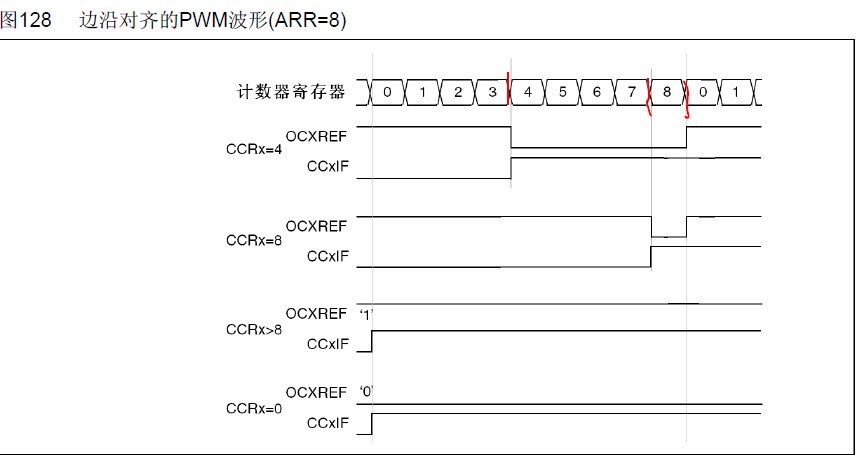
下面是一个PWM模式1的例子。当TIMx_CNT
库函数 STM32F10x_StdPeriph_Lib_V3.3.0\Project\STM32F10x_StdPeriph_Examples\TIM\PWM_Output
主要程序如下:
uint16_t CCR1_Val = 333; // 333/666=0.5 占空比
uint16_t CCR2_Val = 249; // 249/666=0.374
uint16_t CCR3_Val = 166; // 166/666=0.25
uint16_t CCR4_Val = 83; // 83/666 =0.125
uint16_t PrescalerValue = 0;
/* Private function prototypes -----------------------------------------------*/
void RCC_Configuration(void);
void GPIO_Configuration(void);
/* Private functions ---------------------------------------------------------*/
/**
* @brief Main program
* @param None
* @retval None
*/
int main(void)
{
/*! this is done through SystemInit() function which is called from startup
file (startup_stm32f10x_xx.s) before to branch to application main.
To reconfigure the default setting of SystemInit() function, refer to
system_stm32f10x.c file
*/
/* System Clocks Configuration */
RCC_Configuration();
/* GPIO Configuration */
GPIO_Configuration();
/* -----------------------------------------------------------------------
TIM3 Configuration: generate 4 PWM signals with 4 different duty cycles:
The TIM3CLK frequency is set to SystemCoreClock (Hz), to get TIM3 counter
clock at 24 MHz the Prescaler is computed as following:
- Prescaler = (TIM3CLK / TIM3 counter clock) - 1
SystemCoreClock is set to 72 MHzfor Low-density, Medium-density, High-density
and Connectivity line devices and to 24 MHz for Low-Density Value line and
Medium-Density Value line devices
The TIM3 is running at 36 KHz: TIM3 Frequency = TIM3 counter clock/(ARR + 1)
= 24 MHz / 666 = 36 KHz 36036HZ
TIM3 Channel1 duty cycle = (TIM3_CCR1/ TIM3_ARR)* 100 = 50%
TIM3 Channel2 duty cycle = (TIM3_CCR2/ TIM3_ARR)* 100 = 37.5%
TIM3 Channel3 duty cycle = (TIM3_CCR3/ TIM3_ARR)* 100 = 25%
TIM3 Channel4 duty cycle = (TIM3_CCR4/ TIM3_ARR)* 100 = 12.5%
----------------------------------------------------------------------- */
/* Compute the prescaler value */
PrescalerValue = (uint16_t) (SystemCoreClock / 24000000) - 1;
/* Time base configuration */
TIM_TimeBaseStructure.TIM_Period = 665;//Autoreload value ARR
TIM_TimeBaseStructure.TIM_Prescaler = PrescalerValue;
TIM_TimeBaseStructure.TIM_ClockDivision = 0;
TIM_TimeBaseStructure.TIM_CounterMode = TIM_CounterMode_Up;
TIM_TimeBaseInit(TIM3, &TIM_TimeBaseStructure);
/* PWM1 Mode configuration: Channel1 */
TIM_OCInitStructure.TIM_OCMode = TIM_OCMode_PWM1;
TIM_OCInitStructure.TIM_OutputState = TIM_OutputState_Enable;
TIM_OCInitStructure.TIM_Pulse = CCR1_Val;/* Set the Capture Compare Register value CCR1 */
TIM_OCInitStructure.TIM_OCPolarity = TIM_OCPolarity_High;
TIM_OC1Init(TIM3, &TIM_OCInitStructure);
// Enables or disables the TIMx peripheral Preload register on CCR1.
TIM_OC1PreloadConfig(TIM3, TIM_OCPreload_Enable);
/* PWM1 Mode configuration: Channel2 */
TIM_OCInitStructure.TIM_OutputState = TIM_OutputState_Enable;
TIM_OCInitStructure.TIM_Pulse = CCR2_Val;
TIM_OC2Init(TIM3, &TIM_OCInitStructure);
TIM_OC2PreloadConfig(TIM3, TIM_OCPreload_Enable);
/* PWM1 Mode configuration: Channel3 */
TIM_OCInitStructure.TIM_OutputState = TIM_OutputState_Enable;
TIM_OCInitStructure.TIM_Pulse = CCR3_Val;
TIM_OC3Init(TIM3, &TIM_OCInitStructure);
TIM_OC3PreloadConfig(TIM3, TIM_OCPreload_Enable);
/* PWM1 Mode configuration: Channel4 */
TIM_OCInitStructure.TIM_OutputState = TIM_OutputState_Enable;
TIM_OCInitStructure.TIM_Pulse = CCR4_Val;
TIM_OC4Init(TIM3, &TIM_OCInitStructure);
TIM_OC4PreloadConfig(TIM3, TIM_OCPreload_Enable);
TIM_ARRPreloadConfig(TIM3, ENABLE);
/* TIM3 enable counter */
TIM_Cmd(TIM3, ENABLE);
while (1)
STM32TimerPWMOutpu 相关文章:
- Windows CE 进程、线程和内存管理(11-09)
- RedHatLinux新手入门教程(5)(11-12)
- uClinux介绍(11-09)
- openwebmailV1.60安装教学(11-12)
- Linux嵌入式系统开发平台选型探讨(11-09)
- Windows CE 进程、线程和内存管理(二)(11-09)