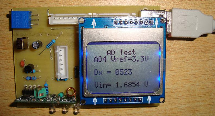
PIC16F917 电压表

/*************PIC16F917单片机程序******************************/
/*********************************************************************/
/*****File Function : AD采集,LCD显示程序*****/
/*****Program Author : ZhengWen(ClimberWin)*****/
/*****MCU : PIC16F917 内部晶振*****/
/*****Compile Date : 2010/08/18 *****/
/*****Edition Info : V1.0 *****/
/*************************************************************/
//测量AD,并且通过LCD来进行显示
//引脚定义:PORTD=8LED,KEY=RB0(INT) RA5(AN4)作为AD输入
/*修改日期: */
/************************************/
#include
#include "english_6x8_pixel.h"
#define uchar unsigned char
#define uint unsigned int
void Init(void); //初始化子程序
void LCD_init(void); //LCD初始化程序
void LCD_clear(void);
void LCD_write_char(unsigned char c);
void LCD_set_XY(unsigned char X, unsigned char Y);
void LCD_write_english_string(unsigned char X,unsigned char Y,const char *s);
void LCD_write_byte(unsigned char data, unsigned char command);
void delayms(unsigned int count);
void interrupt ADint(void);
#define KEY RB0
#define SPI_CLK RD0
#define SPI_MOSI RD1
#define LCD_DC RD2
#define LCD_CE RD3
#define LCD_RST RD4
/***********************************************/
const unsigned char mask_table[8]={0x80,0x40,0x20,0x10,0x08,0x04,0x02,0x01};
float ad_data;//AD数据存储地址
uchar temp1,temp2;
uint temp3;
/*********************************************/
void delayms(unsigned int count)
{
uint i,j;
for(i=0;i
}
/*********************************************/
void Init(void)
{
PORTA = 0B00000000;
PORTB = 0B00000000;
PORTD = 0B00000000;
TRISA = 0B00100010;//设置RA5(AN4) RA1作为输入
TRISB = 0B00100001;//设置RB0为输入,作为按键口
TRISD = 0B00000000;//设置PORTD口为输出,作为LCD/LED显示口
RD5=1;//关闭LED
RD6=1;
RD7=1;
///////////AD配置///////////////////////////////////////
ANSEL= 0B00010000; //选择AN4作为AD输入 (PDF 148)
ADCON0=0B10010001;//AD结果格式Right justified,选择参考电压VDD-VSS,AN4输入,关闭AD转换
ADCON1=0B01010000; //AD转换时钟选择
ADIE=1;//AD中断使能
PEIE=1;
ADIF=0;//清除中断标志位
GIE=1; //开总中断
/////////////////////////////////////
LCD_init(); //初始化液晶
}
void interrupt ADint(void)
{
temp1=ADRESL;
temp2=ADRESH;
temp3=temp2*256+temp1; //Dx值
ad_data=(temp3*33000)/1024; //电压值
ADIF=0;//清除中断标志位
}
void LCD_init(void)
{
LCD_RST=0; //LCD复位
NOP();
LCD_RST=1;
LCD_CE=0 ;// 关闭LCD
NOP();
LCD_CE=1;// 使能LCD
NOP();
LCD_write_byte(0x21, 0);// 使用扩展命令设置LCD模式
LCD_write_byte(0xc8, 0);// 设置偏置电压
LCD_write_byte(0x06, 0);// 温度校正
LCD_write_byte(0x13, 0);// 1:48
LCD_write_byte(0x20, 0);// 使用基本命令
LCD_clear(); // 清屏
LCD_write_byte(0x0c, 0);// 设定显示模式,正常显示
LCD_CE=0 ; // 关闭LCD
}
/////////LCD清屏程序/////////////
void LCD_clear(void)
{
uint i;
LCD_write_byte(0x0c, 0);
LCD_write_byte(0x80, 0);
for (i=0; i<504; i++)
LCD_write_byte(0x00, 1);//清零
}
///////////设置LCD坐标///////////////////
void LCD_set_XY(unsigned char X, unsigned char Y)
{
LCD_write_byte(0x40 | Y, 0);
LCD_write_byte(0x80 | X, 0);
}
////////////////字符显示程序/////////////////////
void LCD_write_char(unsigned char c)
{
uint line;
c=c-32;
for (line=0; line<6; line++)
LCD_write_byte( FONT6x8[c][line], 1);
}
/////////////////打印字符串/////////////////////////
void LCD_write_english_string(unsigned char X,unsigned char Y, const unsigned char *s)
{
uchar i = 0;
LCD_set_XY(X,Y);
while(*s) {LCD_write_char(*s++);}
}
////////////写数据到LCD//////////////////////
void LCD_write_byte(unsigned char data, unsigned char command)
{
uchar i;
LCD_CE=0 ; // 使能LCD
if (command == 0)
{LCD_DC=0 ;} // 传送命令
else
{LCD_DC=1 ;} // 传送数据
for(i=0;i<8;i++)
{
if(data&mask_table[i])
{SPI_MOSI=1;}
else
{SPI_MOSI=0;}
SPI_CLK=0;
NOP();
SPI_CLK=1;
}
PIC16F917电压 相关文章:
- Windows CE 进程、线程和内存管理(11-09)
- RedHatLinux新手入门教程(5)(11-12)
- uClinux介绍(11-09)
- openwebmailV1.60安装教学(11-12)
- Linux嵌入式系统开发平台选型探讨(11-09)
- Windows CE 进程、线程和内存管理(二)(11-09)
