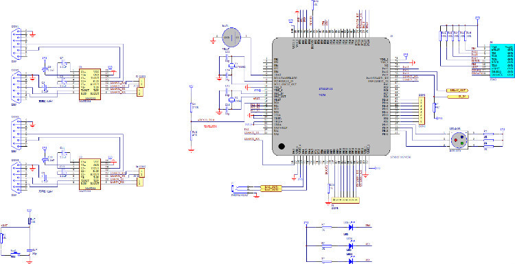
STM32F103V 4串口电路
原理图:
PCB:

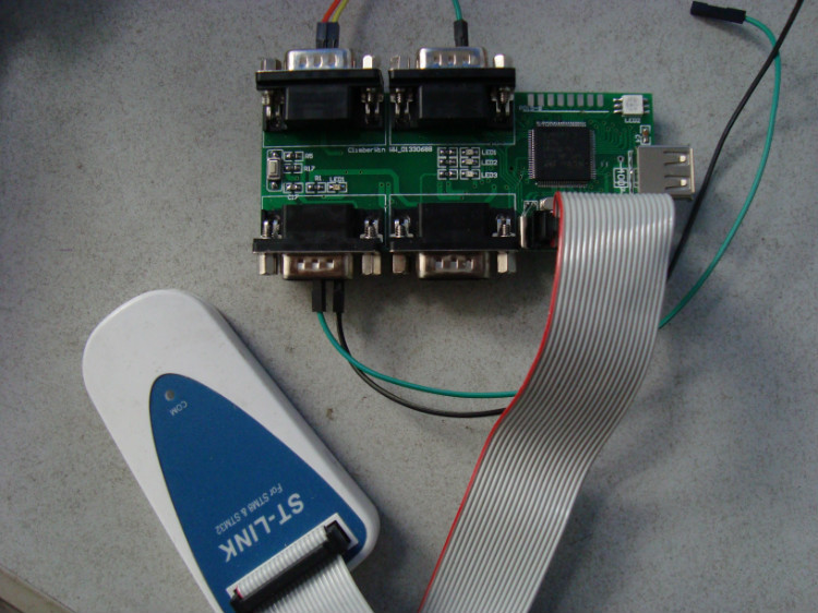
实物图:


串口中断相关的程序段:
void GPIO_Configuration(void)
{
RCC_APB2PeriphClockCmd( RCC_APB2Periph_USART1 |RCC_APB2Periph_GPIOA | RCC_APB2Periph_GPIOB |
RCC_APB2Periph_GPIOC | RCC_APB2Periph_GPIOD |
RCC_APB2Periph_GPIOE, ENABLE);
GPIO_InitStructure.GPIO_Pin = GPIO_Pin_9|GPIO_Pin_13|GPIO_Pin_14|GPIO_Pin_15;//LED1+RGB LED
GPIO_InitStructure.GPIO_Mode = GPIO_Mode_Out_PP;
GPIO_InitStructure.GPIO_Speed = GPIO_Speed_50MHz;
GPIO_Init(GPIOB, &GPIO_InitStructure);
GPIO_InitStructure.GPIO_Pin = GPIO_Pin_0|GPIO_Pin_1;//LED2+LED3
GPIO_InitStructure.GPIO_Mode = GPIO_Mode_Out_PP;
GPIO_InitStructure.GPIO_Speed = GPIO_Speed_50MHz;
GPIO_Init(GPIOE, &GPIO_InitStructure);
GPIO_InitStructure.GPIO_Pin = GPIO_Pin_9; //USART1 TX
GPIO_InitStructure.GPIO_Mode = GPIO_Mode_AF_PP; //复用推挽输出
GPIO_Init(GPIOA, &GPIO_InitStructure); //A端口
GPIO_InitStructure.GPIO_Pin = GPIO_Pin_10; //USART1 RX
GPIO_InitStructure.GPIO_Mode = GPIO_Mode_IN_FLOATING; //复用开漏输入
GPIO_Init(GPIOA, &GPIO_InitStructure);
GPIO_InitStructure.GPIO_Pin = GPIO_Pin_2; //USART2 TX
GPIO_InitStructure.GPIO_Mode = GPIO_Mode_AF_PP; //复用推挽输出
GPIO_Init(GPIOA, &GPIO_InitStructure); //A端口
GPIO_InitStructure.GPIO_Pin = GPIO_Pin_3; //USART2 RX
GPIO_InitStructure.GPIO_Mode = GPIO_Mode_IN_FLOATING; //复用开漏输入
GPIO_Init(GPIOA, &GPIO_InitStructure); //A端口
GPIO_InitStructure.GPIO_Pin = GPIO_Pin_10; //USART3 TX
GPIO_InitStructure.GPIO_Mode = GPIO_Mode_AF_PP; //复用推挽输出
GPIO_Init(GPIOB, &GPIO_InitStructure); //B端口
GPIO_InitStructure.GPIO_Pin = GPIO_Pin_11; //USART3 RX
GPIO_InitStructure.GPIO_Mode = GPIO_Mode_IN_FLOATING; //复用开漏输入
GPIO_Init(GPIOB, &GPIO_InitStructure); //B端口
GPIO_InitStructure.GPIO_Pin = GPIO_Pin_10; //USART4 TX
GPIO_InitStructure.GPIO_Mode = GPIO_Mode_AF_PP; //复用推挽输出
GPIO_Init(GPIOC, &GPIO_InitStructure); //B端口
GPIO_InitStructure.GPIO_Pin = GPIO_Pin_11; //USART4 RX
GPIO_InitStructure.GPIO_Mode = GPIO_Mode_IN_FLOATING; //复用开漏输入
GPIO_Init(GPIOC, &GPIO_InitStructure); //C端口
}
void NVIC_Configuration(void)
{
NVIC_InitTypeDef NVIC_InitStructure;
/* Configure the NVIC Preemption Priority Bits */
NVIC_PriorityGroupConfig(NVIC_PriorityGroup_1);
/* Enable the USART1 Interrupt */
NVIC_InitStructure.NVIC_IRQChannel = USART1_IRQn; //中断通道为RTC全局中断
NVIC_InitStructure.NVIC_IRQChannelPreemptionPriority = 1;//抢占优先级为1
NVIC_InitStructure.NVIC_IRQChannelSubPriority = 0; //副优先级为0
NVIC_InitStructure.NVIC_IRQChannelCmd = ENABLE;
NVIC_Init(&NVIC_InitStructure);
//选择串口2中断
NVIC_InitStructure.NVIC_IRQChannel = USART2_IRQn; //中断通道为RTC全局中断
NVIC_InitStructure.NVIC_IRQChannelPreemptionPriority = 0;//抢占优先级为1
NVIC_InitStructure.NVIC_IRQChannelSubPriority = 1; //副优先级为0
NVIC_InitStructure.NVIC_IRQChannelCmd = ENABLE;
NVIC_Init(&NVIC_InitStructure);
}
void USARTx_configuration(void)
/* USART1 、USART2 和 USART3 UART4 配置如下:
- 波特率 = 9600
- 字节 = 8 Bits
- One Stop Bit
- No parity
- Hardware flow control disabled (RTS and CTS signals)
- Receive and transmit enabled
*/
{
USART_InitStructure.USART_BaudRate = 9600;
USART_InitStructure.USART_WordLength = USART_WordLength_8b;
USART_InitStructure.USART_StopBits = USART_StopBits_1;
USART_InitStructure.USART_Parity = USART_Parity_No;
USART_InitStructure.USART_HardwareFlowControl = USART_HardwareFlowControl_None;
USART_InitStructure.USART_Mode = USART_Mode_Rx | USART_Mode_Tx;
/* Configure USART1 */
USART_Init(USART1, &USART_InitStructure);
USART_Init(USART2, &USART_InitStructure);
USART_Init(USART3, &USART_InitStructure);
USART_Init(UART4, &USART_InitStructure);
/* Enable USART1 Receive and Transmit
STM32F103V串口电 相关文章:
- Windows CE 进程、线程和内存管理(11-09)
- RedHatLinux新手入门教程(5)(11-12)
- uClinux介绍(11-09)
- openwebmailV1.60安装教学(11-12)
- Linux嵌入式系统开发平台选型探讨(11-09)
- Windows CE 进程、线程和内存管理(二)(11-09)