跨阻再次罢工:利用MDACs实现电流电压转换
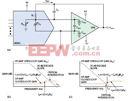
乘法D/A转换器(MDACs)和其后置放大器搭建了数字到模拟世界的桥梁。MDACs产生与输入数字编码成比例的电流值(如图1所示)。后置放大器转换DAC输出的电流信号为电压值。利用DAC、放大器和电阻,简单的电流-电压转换似乎很容易实现。然而,这个电路的稳定性存在问题。

这样应用,MDAC的输出模式包括可变电流源、电阻和电容(图1a)。输出电阻和电容值取决于DAC的输入编码。一般来说,设计MDAC到0刻度会导致输出电阻接近无穷大。设计DAC到满量程或任意值,输出电阻应等于反馈电阻RF值。(参见生产厂商数据手册)。根据内部门极结点通过MDAC输出数据,DAC的输出电容CD也随输入编码而变化。在满量程处,MDAC的输出电容等于数据手册中标准值。在零点,MDAC的输出电容等于约等于满量程值的一半。从稳定性考虑,使用满量程时RD和CD的输出值。
放大器反馈网络是二阶子网络。为保证精度,大多数MDACs有一个片上反馈电阻。反馈电容CF是分开的。
最后,运算放大器有一系列规格指标,但对MDAC电路的稳定性没有影响:单位增益带宽fU,输入差分电容CDIF和共模电容CCM。
在这个系统中,放大器输入的总电容等于CIN=CD+CDIF+CCM。在图1b和图1c中,闭环零点等于f1=1/(2π(CIN+CF)(RD||RF))。闭环极点等于f2=1/(2πCFRF)。
如果开放与闭环增益曲线之间的闭合速度等于20dB/decade,就能确保系统稳定。为了达到这样的效果,选择一个单位增益带宽小于f1或大于f2的放大器。
如果f1大于放大器带宽,很容易设计出稳定电路:
另一方面,如果f2低于开放与闭环增益曲线的交叉点,则使用:
利用这些反馈电容的计算值作为测试电路的出发点。出现电路寄生效应,器件制造偏差等问题,可以尝试改变反馈电容值。
稳定MDAC的模拟信号是关键。然而,也要考虑放大器的噪声、输入偏置电流、偏置电压、MDAC分辨率和毛刺能量等因素。
英文原文:
Transimpedance strikes again: Current-to-voltage conversion with MDACs
Current-to-voltage conversion seems easy to implement with a DAC, amplifier, and resistor. But beware of stability issues.
By Bonnie Baker -- EDN, 7/5/2007
Multiplying DACs (MDACs) and their postamplifiers bridge the digital and analog worlds. MDACs generate a current proportional to an input digital code (Figure 1). The postamplifier converts the DAC’s current-output signal to a voltage level. A simple current-to-voltage conversion seems easy to implement with a DAC, amplifier, and resistor. However, this circuit presents stability issues.
For the application, the output model of the MDAC contains a variable current source, resistor, and capacitor (Figure 1a). The value of the output resistance and capacitance depends on the input code to the DAC. In general, programming the MDAC to zero scale causes the output resistance, RD, to be near infinite. When you program the DAC to full-scale or all ones, this resistance is equal to the feedback resistance, RF. (See the manufacturer’s data sheets.) The DAC’s output capacitance, CD, also varies with input code according to the number of internal gate-source junctions across the MDAC output. At full-scale, the MDAC output capacitance equals the data-sheet specification. At zero, the MDAC output capacitance is equal to about half the full-scale value. For stability calculations, use the full-scale output values of RD and CD.
The second subnetwork is the amplifier-feedback network. To maintain precision, most MDACs have a feedback resistor on-chip. The feedback capacitor, CF, is discrete.
Finally, op amps have a range of specifications, but only a few affect the MDAC circuit’s stability: unity-gain bandwidth, fU; input differential capacitance, CDIF; and common-mode capacitance, CCM.
In this system, total capacitance at the amplifier input is equal to CIN=CD+CDIF+CCM. In Figure 1b and Figure 1c, the closed-loop zero is equal to f1=1/(2π(CIN+CF)(RD||RF)). The closed-loop pole is equal to f2=1/(2πCFRF).
You ensure system stability if the
电流 电压 转换 实现 MDACs 罢工 利用 再次 相关文章:
- 电源设计小贴士 1:为您的电源选择正确的工作频率(12-25)
- 用于电压或电流调节的新调节器架构(07-19)
- 超低静态电流电源管理IC延长便携应用工作时间(04-14)
- 电源设计小贴士 2:驾驭噪声电源(01-01)
- 负载点降压稳压器及其稳定性检查方法(07-19)
- 电源设计小贴士 3:阻尼输入滤波器(第一部分)(01-16)
