压电式能量收集解决方案
简介:
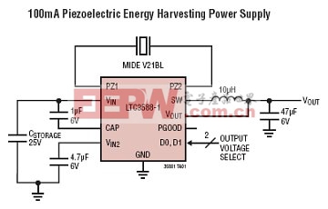
无线传感器均凭借其与众不同的特性而成为无线传感网中的重要成员。在这些应用中,能量收集技术能够在不采用主要电池的情况下解决供电问题。LTCreg;3588-1 集成了一个低损失全波桥式整流器和一个高效率降压型转换器,以造就一款专为高输出阻抗能源 (例如:压电换能器) 而优化的完整能量收集解决方案。
特性介绍:
LTCreg;3588-1 集成了一个低损失全波桥式整流器和一个高效率降压型转换器,以造就一款专为高输出阻抗能源 (例如:压电换能器) 而优化的完整能量收集解决方案。一种具有一个宽迟滞窗口的超低静态电流欠压闭锁 (UVLO) 模式允许电荷在一个输入电容器上积聚,直到降压型转换器能够有效地将一部分存储电荷转移至输出为止。当处于调节模式时,LTC3588-1 将进入一种睡眠状态 (在该状态中,输入和输出静态电流都非常小)。降压型转换器根据需要接通和关断,以保持调节作用。
可通过引脚来选择 4 种输出电压 (1.8V、2.5V、3.3V 和 3.6V),连续输出电流高达 100mA;然而,可以选择合适大小的输出电容器来提供一个较高的输出电流脉冲。对于某个给定的输入电容值,一个设定在 20V 的输入保护性分路器实现了较高的能量存储。
1500nA 输入静态电流 (输出处于调节状态 —— 无负载,VIN = 18V) 在 UVLO 模式中的输入静态电流为 830nA (VIN = 12V) 14V 至 20V 输入工作范围 集成的低损失全波桥式整流器 16V UVLO 改善了采用高电压电流受限型输入时的功率利用率 高达 100mA 的输出电流 高效率集成迟滞降压型 DC/DC 转换器 可选的输出电压:3.45V、4.1V、4.5V、5.0V 输入保护性分路器 —— 高达 25mA 的下拉电流 (在 VIN ≥ 20V) 采用10 引脚 MSE 封装和 3mm x 3mm DFN 封装 
图1 典型应用
方案特点:
Thecircuitisanenergyharvestingpower supplyfeaturingthe LTC3588-1/LTC3588-2.
An ultralow quiescent current undervoltagelockout mode with a wide hysteresis windowallows charge to accumulate on an input capacitor until the buck converter can efficiently transfer a portion of the stored charge to the output. Four outputvoltages are pin selectable with up to 100mA of continuousoutput current. A power good comparator produces a logic high referenced to VOUT on the PGOOD pin when the converter reaches the programmed VOUT, signaling that the output is in regulation.
A power good comparator produces a logic high referencedto VOUT on the PGOOD pin the first time the converter reaches the programmed VOUT, signaling that the output is in regulation. The PGOOD pin will remain high until VOUT falls to 92% of the desired regulated voltage.
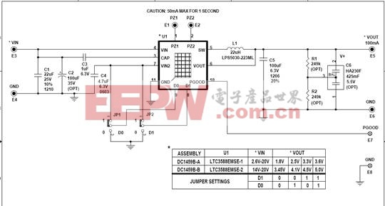
方案原理图:
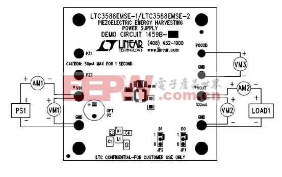
方案PCB图:
- 大联大控股世平推出高性能电机控制解决方案(04-11)
- “可持续性”模块电源解决方案(01-26)
- 反激式电源中的常见噪声来源及可操作的解决方案(12-27)
- 基于Fairchild和NXP产品的电源解决方案(12-10)
- 工业交换机行业电源解决方案(11-12)
- 电源测试一体化解决方案(09-28)
