如何实现DS34S132与其它TDMoP器件的互操作
时间:02-16
来源:互联网
点击:
| IPVER | IP version number; IPv4 IPVER = 4 |
| IHL | Length in 32-bit words of the IP Header, IHL = 5 |
| IP TOS | IP type of service |
| Total length | Length in octets of IP Header and data |
| Identification | IP fragmentation identification |
| Flags | IP control flags; must be set to 010 to avoid fragmentation |
| Fragment offset | Indicates where in the datagram the fragment belongs; not used for TDMoP |
| Time to live | IP time-to-live field; datagrams with zero in this field are discarded |
| Protocol | Must be set to 0x11 to signify UDP |
| IP Header checksum | Checksum for the IP Header |
| Source IP address | IP address of the source |
| Destination IP address | IP address of the destination |
表3. UDP报头结构
| Field | Description |
| Source port number, destination port number | Either the source or the destination port number holds the bundle identifier. The unused field can be set to 0x85E (2142), which is the user's port number assigned to TDMoP by the Internet Assigned Numbers Authority (IANA). For UDP/IP-specific OAM packets, the bundle identifier is all 1s. |
| UDP length | Length in octets of UDP Header and data |
| UDP checksum | Checksum of UDP/IP Header and data. If not computed, it must be set to zero. |
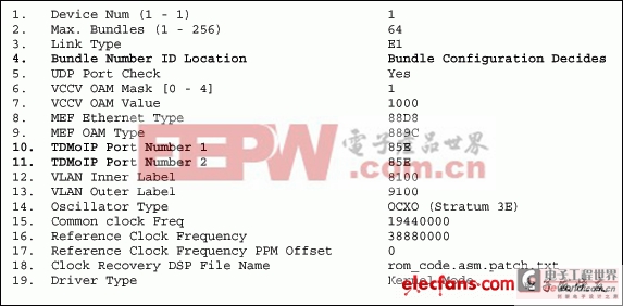
根据IANA规定,UDP报头的目标端口应设定为0x85E (2142),这是分配给TDMoP的用户端口号。Maxim TDMoP器件默认遵循该规范。
部分TDMoP厂商在UDP报中的目标端口号位置分配一个绑定标识号,而不是在源端口号位置。有些厂商还分配一个随机号作为用户端口号,而不是采用IANA分配的0x85E。使用DS34S132时,用户可采用两种方式解决这些问题。
- 在预配置菜单中,将全部绑定标识号赋予相应的位置。
- 向绑定引擎表明绑定标识号在接收数据包中的位置。
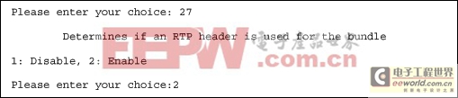
- RTP报头互操作性
RTP报头
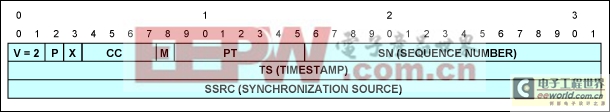
Field Description V RTP version; must be set to 2. P Padding bit; must be set to 0. X Extension bit; must be set to 0. CC CSRC count; must be set to 0. M Marker bit; must be set to 0. PT Payload type. One PT value MUST be allocated from the range of dynamic values for each direction of the bundle. The same PT value MAY be reused for both directions of the bundle, and is also reused between different bundles. SN The sequence number identical to the sequence number in the control word. TS Timestamp. The RTP Header can be used in conjunction with the following modes of timestamp generation:
Absolute mode: the chip sets timestamps using the clock recovered from the incoming TDM circuit.
Differential (common clock) mode: The two chips at bundle edges have access to the same high-quality clock source, and this clock source is used for timestamp generation.SSRC Identifies the synchronization source. This identifier should be chosen randomly, with the intent that no two synchronization sources within the same RTP session will have the same SSRC identifier. 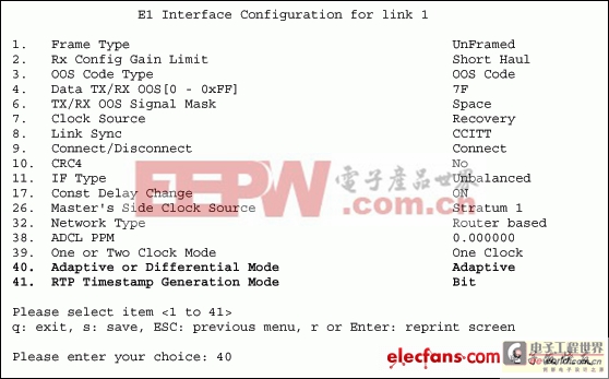
如何区分其他厂商TDMoP器件的报文内容
总结
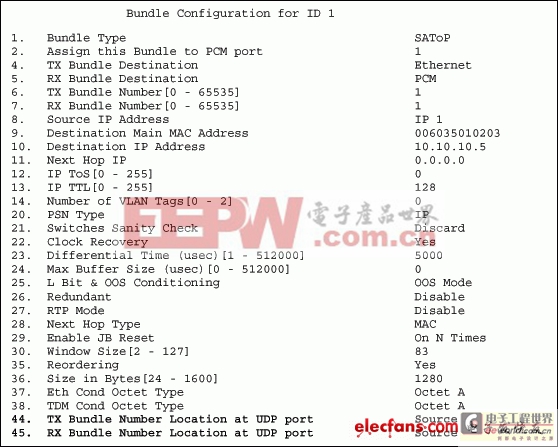
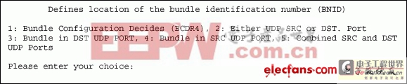
- 向绑定引擎表明绑定标识号在接收数据包中的位置。参考上文中的图4,选项1,Bundle Configuration Decides (BCDR4),将在目标端口号或源端口号位置分配一个绑定标识号,取决于图5中所示的绑定配置。
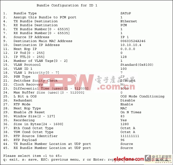
图5. DS34S132的绑定配置菜单。
在以上的绑定配置菜单中,用户在UDP源端口号位置插入绑定标识号。用户还表明报文分类模块应该在UDP源端口号位置查找绑定标识号。
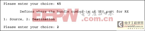
如果用户知道数据包的绑定标识号位于UDP目标端口号位置,那么则很容易通过将选项45, RX Bundle Number Location at UDP port,修改为Destination进行表示,如图6所示。
图6. DS34S132的绑定配置菜单的选项45。
图7. RTP报头
表4. RTP报头结构
为了在绝对时钟恢复模式下产生时钟,端口接收配置寄存器4 (PRCR4)中的RTP发生器时标模式选择(TSGMS)位需设定为1,即PRCR4.TSGMS = 1。为了在差分时钟恢复模式产生时钟,PRCR4寄存器中的TSGMS位需设定为0,即PRCR4.TSGMS = 0。用户无需手动设置这些寄存器位。在绑定配置中将RTP使能时,这些位被设置。
自适应模式下, Maxim的DS34S132 TDMoP器件中的时钟恢复算法根据数据包之间到达延迟恢复时钟。因此,自适应时钟恢复模式下,使能RTP是可选的。然而,差分模式下, Maxim的DS34S132 TDMoP器件中的时钟恢复算法通过分析RTP报头中的时标恢复时钟。所以,差分时钟恢复模式下,强制使能RTP。
为了实现互操作,用户需要确定其它TDMoP厂商用以发生RTP报头中时标的模式。用户还需要了解其它系统处于自适应还是差分时钟恢复模式。在接口配置中,可更改每个端口的时钟恢复模式。图8所示为如何修改时钟恢复模式。默认为自适应模式端口。
图8. 接口配置。
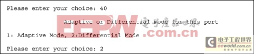
现在,如果用户希望更改时钟恢复模式,那么就需要使用选项40,Adaptive or Differential mode,如图9所示。
图9. 在接口配置中选择差分时钟恢复模式。
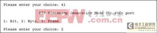
与Maxim的TDMoP器件不同,有些TDMoP厂商在自适应或差分时钟恢复模式下根据RTP报头中的时标恢复时钟。因此,为了实现与这些厂商系统的互操作, Maxim TDMoP器件在自适应时钟恢复模式下使能RTP。DS34S132,以及其它TDMoP厂商的器件,能够以三种方式在RTP报头中产生时标:
- 12位串行A/D转换器MAX187的应用(10-06)
- AGC中频放大器设计(下)(10-07)
- 低功耗、3V工作电压、精度0.05% 的A/D变换器(10-09)
- PIC16C5X单片机睡眠状态的键唤醒方法(11-16)
- 用简化方法对高可用性系统中的电源进行数字化管理(10-02)
- 利用GM6801实现智能快速充电器设计(11-20)