各位大师帮忙分析下这个电路的工作原理
这是英特尔PC7系列的RTC电路,本人刚接触电路分析,还看不懂此电路,望各位高手帮忙详细分析下工作原理,谢谢先!
英特尔PCH7系列RTC电路原理
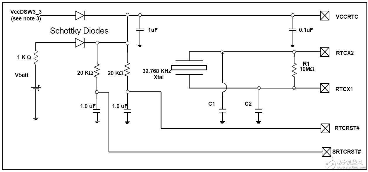
右边有5个引脚,就凭我自己感觉说一下,第一个,供电引脚,第二个和第三个是晶振引脚,第四个和第五个是上电复位引脚,上电后先低电平,然后拉高
第一个是电源,可以看到它有两部分构成,一个是Vbatt,一个是VCCDSW,在poweroff的状态是有Vbatt供电,维持部分电路的供电和相关电平,而当poweron的时候,Vbatt点的肖特基二极管就反相截止了,对Vbatt是一个保护。第二是外部晶体的电路,就是简单的输入输出,标准的。
感谢两位老师的指点,大体上我听明白了。
这是主板电路 南桥的一小部分
即RTC电路
最后一个信号:SRTCRST# is used to reset portions of the Intel Manageability Engine and should not be
connected to a jumper or button on the platform. The only time this signal gets
asserted (driven low in combination with RTCRST#) should be when the coin cell
battery is removed or not installed and the platform is in the G3 state. Pulling this
signal low independently (without RTCRST# also being driven low) may cause the
platform to enter an indeterminate state. Similar to RTCRST#, it is imperative that
SRTCRST# not be pulled low in the S0 to S5 states.
好东西 赞一个
多谢分享!
多谢分享!
领教了!多谢各位大侠!
领教了!多谢各位大侠!
yi lou he er lou shuo de dou you dao li