用quartus II软件和大西瓜开发板 做频率计的实验,如何减小输出频率的误差?
详情请看EDA技术与VHDL第4版潘松编著(清华大学出版社)实验4-5
本人已经做好所有的原理图和程序,就是不知道如何降低输出的误差
比如我分频计用的是20分频,但是输出显示的是21
使用的分频器程序
library ieee;
use ieee.std_logic_1164.all;
use ieee.std_logic_arith.all;
use ieee.std_logic_unsigned.all;
entity fenpin is
port(clk: in std_logic;clk0_5Hz:out std_logic);
end fenpin;
architecture segled of fenpin is
begin
p1:process(clk)
variable count:integer range 0 to 6249999;
begin
if clk'event and clk='1' then
if count<=3124999 then
clk0_5Hz<='0';
count:=count+1;
elsif count>3124999 and count<=6249999 then
clk0_5Hz<='1';
count:=count+1;
else count:=0;
end if;
end if;
end process p1;
END ARCHITECTURE SEGLED;
测试用的分频器程序library ieee;
use ieee.std_logic_1164.all;
use ieee.std_logic_arith.all;
use ieee.std_logic_unsigned.all;
entity fenpin1 is
port(clk: in std_logic;clk1Hz:out std_logic);
end fenpin1;
architecture segled of fenpin1 is
begin
p1:process(clk)
variable count:integer range 0 to 49999999;
begin
if clk'event and clk='1' then
if count<=24999999 then
clk1Hz<='0';
count:=count+1;
elsif count>24999999 and count<=49999999 then
clk1Hz<='1';
count:=count+1;
else count:=0;
end if;
end if;
end process p1;
END ARCHITECTURE SEGLED;
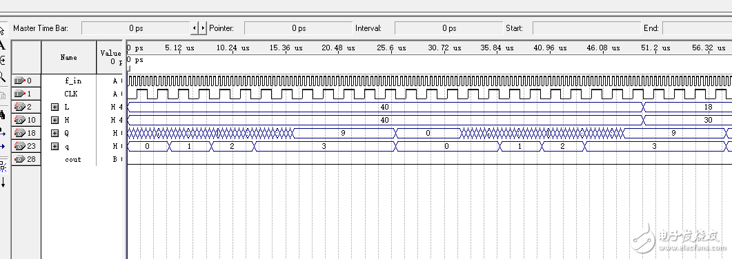
频率计工作时序波形.png(23.65 KB, 下载次数: 0)
下载附件 保存到相册
2015-11-6 13:54 上传
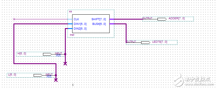
xs2.png(16.75 KB, 下载次数: 4)
下载附件 保存到相册
2015-11-6 13:49 上传
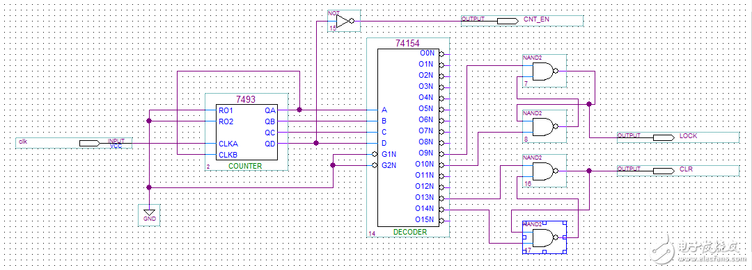
测频时序控制电路.png(32.75 KB, 下载次数: 7)
下载附件 保存到相册
2015-11-6 13:49 上传
测频时序控制电路工作波形.png(13.53 KB, 下载次数: 1)
下载附件 保存到相册
2015-11-6 13:49 上传

含有时钟使能的两位十进制计数器.png(32.71 KB, 下载次数: 0)
下载附件 保存到相册
2015-11-6 13:49 上传
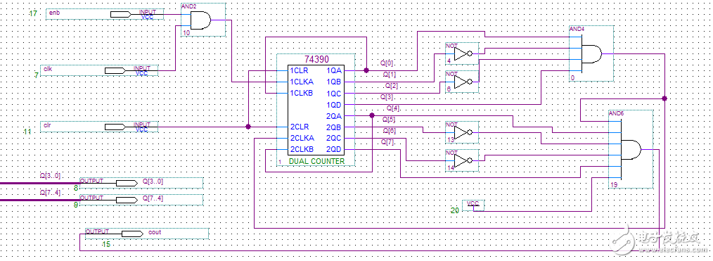
两位十进制计数器工作波形.png(19.13 KB, 下载次数: 0)
下载附件 保存到相册
2015-11-6 13:49 上传

两位十进制频率计测频率计测频仿真波形.png(22.69 KB, 下载次数: 5)
下载附件 保存到相册
2015-11-6 13:49 上传

频率计顶层电路原理图.png(40.24 KB, 下载次数: 2)
下载附件 保存到相册
2015-11-6 13:49 上传
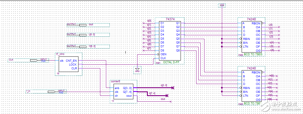
频率计工作时序电路.png(23.65 KB, 下载次数: 0)
下载附件 保存到相册
2015-11-6 13:49 上传
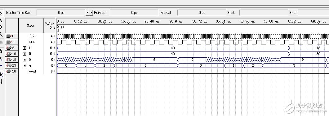
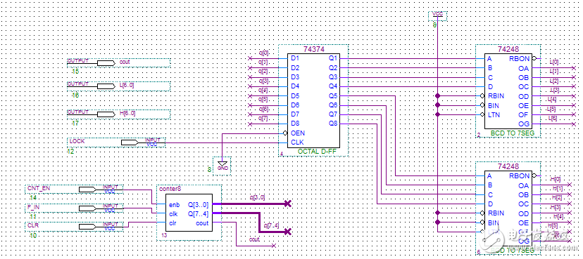
频率计原理图.png(51.89 KB, 下载次数: 4)
下载附件 保存到相册
2015-11-6 13:54 上传
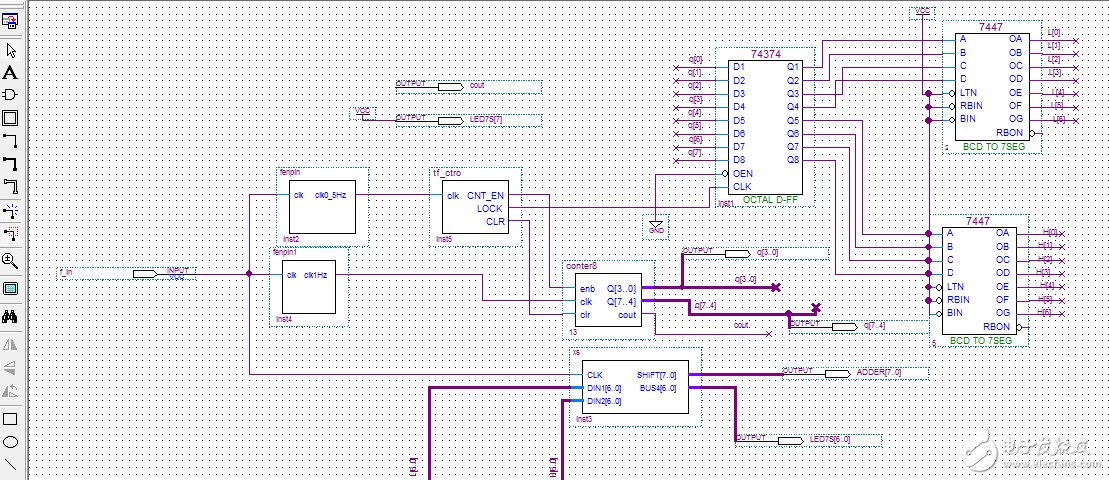
贴上程序,大家好帮你看,可能是你的判断的时候是否漏掉等于号
、
我把程序和原理图都放上去了
我把程序改成上面的了 现在显示是1分频。
quartus II软件是什么?
EDA的一个东西 专门做硬件的一个软件
