Measuring capactiance and inductance
时间:04-06
整理:3721RD
点击:
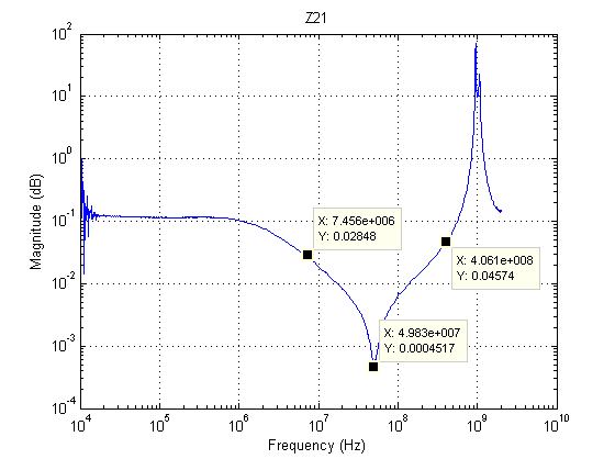
I measured the S21 and converted it to Z params and plotted it.
I understand how before the resonant frequency, the capacitance dominates then
after resonance the inductance dominates.
I don't understand the second dip at around 1GHz. Why does it go back down?
You didn't clarify the measurement setup. Assuming a LC series circuit connected between port 1 and port 2, you see the inductor self resonance around 1 GHz.
all components tend to have SRF elements, even very carefully controlled impedances and transmission lines.
Can you display S11 to see if there is zero on the input that created a pole on S21?
Measuring capactiance inductance 相关文章: