Quad Coil creation for FM
时间:04-06
整理:3721RD
点击:
Hello,
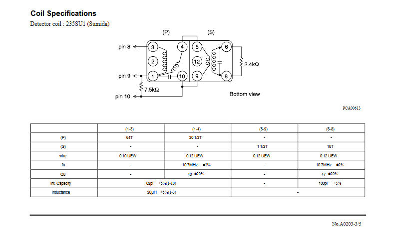
I'm trying to replicate FM quadrature detector coils (because I can't seem to find a supplier
who has them). It is for a 10.7MHz IF, for WB FM. The coils in question are actually several coils
(in two cans glued together), as shown in the diagram/specs here. The specs are very useful, they
show the inductances of some of the coils, the number of turns for all of the coils, the capacitances
and the wire thicknesses:
By looking at the specs above, I'm guessing that all inductances are as follows:
Coil (1-3): 26uH
Coil (1-4): 2.5uH approx
Coil (5-9): 0.015uH approx
Coil (6-8): 2.2uH approx
According to those specs, the two LC tanks are comprised of Coil (6-8) in parallel with 100pF,
and combined coils (1-4) and (5-9) in parallel with 82pF.
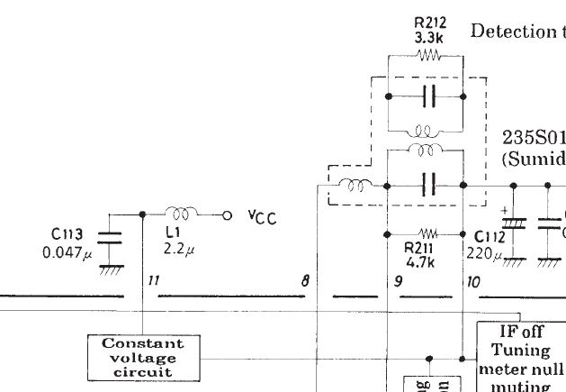
The coils are used in this circuit:
I know how a single LC coil would get used in a quadrature detector, but for this multi-coil design with mutual
inductances, I fear maybe I'm missing something if I assume simplistically that I just need to wind close to
these values and hope for the best.
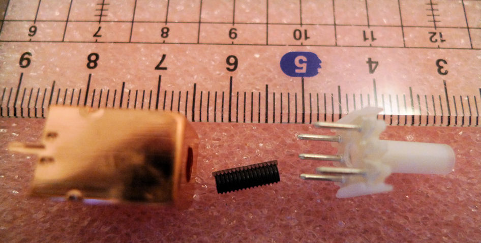
I've found coil formers and ferrite slugs that with the same approx number of turns (as shown on the specs) will result in
the approximate inductances. These are Neosid coil kits, '10 F 1', which can have an Al value of between 6-8nH.
Two of these will be used.
However, since I need to align it for phase symmetry and linearity around 10.7MHz, I'm quite
concerned how I should wind the coils. For example, since the 22uH and 2.5uH coils are on the same former, adjusting the slug will affect both inductances. So, I don't know if I should wind the 2.5uH coil at the bottom of the
former, so that the slug will have most affect on that one first, rather than the 26uH coil.
With the wire thicknesses that are mentioned in the spec, I can wind 26uH and 2.5uH in a single layer to cover just under the entire length of the slug, but I don't know how the original coils were wound, because I don't have them, and I'm only working off the spec.
So, I'd rather like to understand how it was intended to function first, and how a user was expected to tune them and in which order, to achieve the correct response (this is intended for a hi-fi application).
Unfortunately most books and papers seem to only mention the single LC method, rather than this multi-coil design.
If anyone has any insight into this, or a reference, it would be very much appreciated.
I'm trying to replicate FM quadrature detector coils (because I can't seem to find a supplier
who has them). It is for a 10.7MHz IF, for WB FM. The coils in question are actually several coils
(in two cans glued together), as shown in the diagram/specs here. The specs are very useful, they
show the inductances of some of the coils, the number of turns for all of the coils, the capacitances
and the wire thicknesses:
By looking at the specs above, I'm guessing that all inductances are as follows:
Coil (1-3): 26uH
Coil (1-4): 2.5uH approx
Coil (5-9): 0.015uH approx
Coil (6-8): 2.2uH approx
According to those specs, the two LC tanks are comprised of Coil (6-8) in parallel with 100pF,
and combined coils (1-4) and (5-9) in parallel with 82pF.
The coils are used in this circuit:
I know how a single LC coil would get used in a quadrature detector, but for this multi-coil design with mutual
inductances, I fear maybe I'm missing something if I assume simplistically that I just need to wind close to
these values and hope for the best.
I've found coil formers and ferrite slugs that with the same approx number of turns (as shown on the specs) will result in
the approximate inductances. These are Neosid coil kits, '10 F 1', which can have an Al value of between 6-8nH.
Two of these will be used.
However, since I need to align it for phase symmetry and linearity around 10.7MHz, I'm quite
concerned how I should wind the coils. For example, since the 22uH and 2.5uH coils are on the same former, adjusting the slug will affect both inductances. So, I don't know if I should wind the 2.5uH coil at the bottom of the
former, so that the slug will have most affect on that one first, rather than the 26uH coil.
With the wire thicknesses that are mentioned in the spec, I can wind 26uH and 2.5uH in a single layer to cover just under the entire length of the slug, but I don't know how the original coils were wound, because I don't have them, and I'm only working off the spec.
So, I'd rather like to understand how it was intended to function first, and how a user was expected to tune them and in which order, to achieve the correct response (this is intended for a hi-fi application).
Unfortunately most books and papers seem to only mention the single LC method, rather than this multi-coil design.
If anyone has any insight into this, or a reference, it would be very much appreciated.
good ruck. got 40awg wire?
http://hem.passagen.se/communication/ifcan.html
That's an excellent site (I've seen that site before) but unfortunately the design he covers seems different from the dual-can model. The dual-can model presumably gives higher linearity, which is why I want to try it out.
Yes, 40awg is awfully thin : ) I have 38awg (ordered some 40awg) and that is already as thin as a hair!