standing waves, Voltage standing wave ratio and reflection coefficeint
Standing waves are caused by the combination of incident and reflected waves on a transmission line? It appears from my studies that the amplitude of the incident and reflected signal resultant wave depends on the phase of the incident and reflected voltage signal. So if the reflected and incident wave are the same the resultant wave is at its maximum. My question is what is the significance and/or ramifications of having a incident wave combine with a reflected wave to create a resultant wave? If my match between the transmission is pretty close to ideal the resultant wave that occurs between the incident wave and reflected wave will be negligible? What is the ramification of having standing waves? What impact does it have?
Is there a relationship between the reflection coefficient and vswr and standing waves?
Have you seen this webpage?
http://www.microwaves101.com/encyclopedia/vswr.cfm
'Standing waves' are more than just an electrical phenomenon BTW.
RF_Jim
Here you can find the best explanation:
http://www.home.agilent.com/upload/c...ork_2005-1.pdf
VSWR is used because it is (relatively) simple to measure voltage; a slotted line was, and sometimes still is, used for this measurement.
As you say, ISWR could be used; but current measurement of RF is difficult.
There is a simple mathematical relationship between VSWR, Reflection Co-efficient and Return Loss; Google or a basic textbook will be your friend.
Note that all these indicators are scalar quantities; modern techniques of vector analysis give us more information.
uh, because....if you know the voltage on a transmission line...you also know, by inspection, the current.
Would you assert that this proposed technique is equally applicable on a 'flat' (Line Z matched to, or equals the load Z) line, as well as on a line which has a mismatch on the end (Load Z not equal to Transmission Line Z)?
(Yes, this is a trick question!)
RF_Jim
That source you gave doesnt do it for me but thanks for the reply.
- - - Updated - - -
Why does some text coin RL as -20 log(reflection coefficient) and others coin RL as 20 log(reflection coefficient)? Which one is it? on a VNA if I was measuring S11 (Log Mag) the Return Loss aka Reflection Loss would be expressed with a negative number in dB. The more negative the better.
The use of plus or minus for RL is confusing.
I think that the correct useage is plus (or no sign, implying positive).
The reason is that it is return LOSS not return GAIN; return loss is correctly shown as, say, 20dB because there is a loss of 20dB.
If the term were return gain, it would be correct to write -20dB, ie a gain of -20dB or a loss of 20dB.
This is a good demonstration;
http://www.bessernet.com/Ereflecto/tutorialFrameset.htm
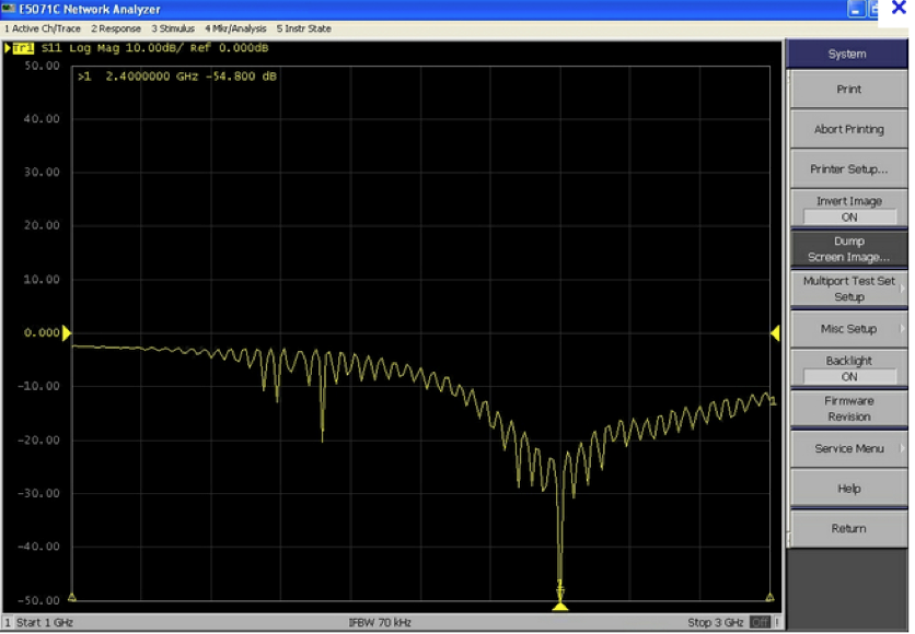
Please look at my S11 (return/reflection loss) log mag plot using VNA. It clearly shows that at 2.4Ghz my return/reflection loss is -54.8 dB. This tells me that I have most energy transfer efficiency at 2.4Ghz. My return loss is expressed as -54.8dB not as 54.8dB. So the VNA goes with the -20log(reflection coefficient) formula instead of the 20log(reflection coefficient) formula. I still dont know why some text use plus and some use minus.
- - - Updated - - -
Yeah I was checking out bessernet for some clarity. Bessernet helped me with seeing the relationships between reflection coefficients, VSWR and RL but one thing i dont get is if reflection coefficient = ZL-Zs/ZL+Zs and ZL=50 and Zs=25 = .33 and RL = 10.4 but if reflection coefficient = ZL-Zs/ZL+Zs and ZL=25 and Zs=50 = -.33 but since RL = 20log(reflection coefficient) you cannot take the log of a negative number so how is bessernet able to determine that a reflection coefficient -.33 is a RL of 10.4? Also what is Z1?
Google "return loss positive negative" and you will find that positive is strictly correct but that negative has "historically" been used.
But your VNA is correct in displaying -54.8 dB; you see, it is not displaying return loss.
It is displaying S1,1 as a log magnitude; the use of a minus sign is correct. S-parameters are the ratio of gozouta to gozinta so if, say, 0 dBm is sent into port 1 and -54.8 dBm is returned from that port, the log mag of S1,1 is -54.8 dB.
If you wished to express this S1,1 as RL you would omit the minus sign and write "a return loss of 54.8 dB".
I think that your confusion involves precisely what is being measured.
When you program your vector network analyzer, there is no button to push that says "return loss". Instead you push the S11 button. As such, a passive device will always reflect back lower wave amplitude than is incident, so |S11| is <1. When you then ask the network analyzer to display that as "dB' format, 20 Log S11 is shown as negative.
If you then want to talk about the measurement as a "return loss", then you remove the "-" signal, since it is a power loss, not a gain, as pointed out above.
- Induced voltages on transmission line by plane wave in HFSS
- Klystron output voltage, cavity field strength
- Negative voltage needed in K-band
- How to set the bias voltage of the BJT in Gilbert mixer
- is DC voltage gain not an important issue to consider in LNA designing?
- Power (Voltage / Current) inducted in rectangle antenna.