2.4ghz discrete balun design
时间:04-06
整理:3721RD
点击:
Im reviewing some of notes on how to design a discrete Balance to Single Ended circuit. I require a BALUN to connect a differential pins (P and N) of the cc2400 to a 50 coaxial patch antenna.
I attached the notes Im using to this post.
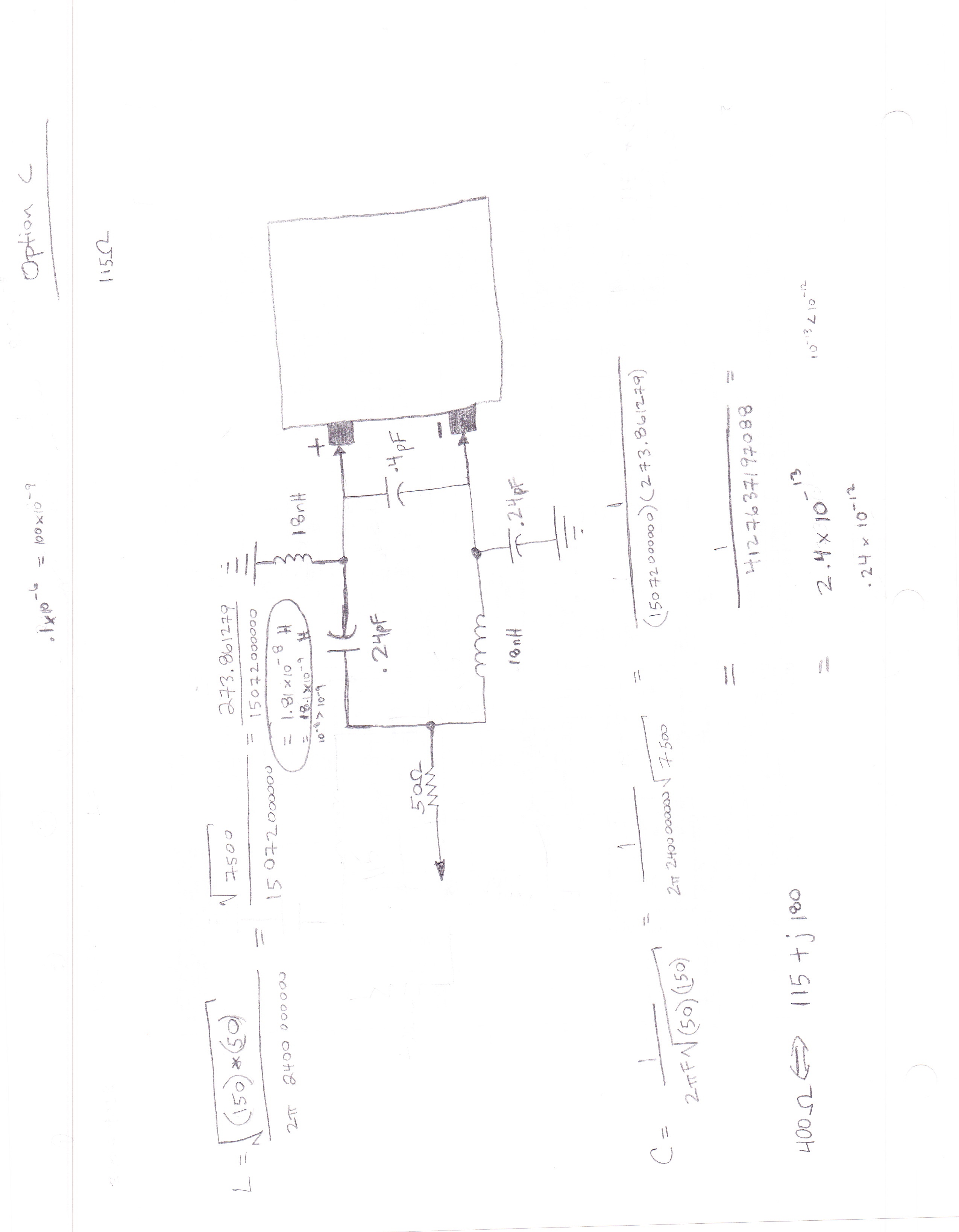
What is troubling me is how L (inductor) is calculated. L = [sqrt (Rsource*Rload)]/2pif.
As you can see Rload is 150 and Rsource is 50. I follow how Rsource is obtained but where is 150 coming from for Rload?
115 + j180 is the load impedance according to TI cc2400 spec.
I attached the notes Im using to this post.
What is troubling me is how L (inductor) is calculated. L = [sqrt (Rsource*Rload)]/2pif.
As you can see Rload is 150 and Rsource is 50. I follow how Rsource is obtained but where is 150 coming from for Rload?
115 + j180 is the load impedance according to TI cc2400 spec.
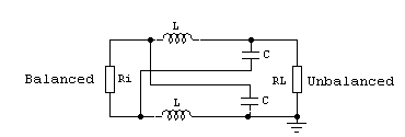
Assuming Ri is the input balanced resistance, and RL is output unbalanced resistance, we get Zc (Impedance conversion): Zc = SQRT (Ri x RL)
L and C will be:
L = Zc / (2*Pi*f)
C = 1 / (Zc*2*Pi*f)
An LC balun it will work only at one frequency.
So Ri = 50 Ohms and RL = 115 Ohms? Please confirm.
That's right.
The input impedance of the device is 115+j118. The imaginary part which actually is a inductance is resonated by a parallel capacitor with value 0.4pF. So only a real part of 115ohm will be used to calculate the balun component value.