Differential Load Impedance Match [Math]
I want to match this using lumped components (capacitors and inductors). Where is the easiest place to start on paper?
e.g.
What math do I begin with?
Thank you,
What type of matching do you want to do? Balanced, unbalanced, impedance?
I want to connect an antenna so I guess convert to unbalanced?
The matching you want to do is probable two things:
1. Convert from balanced to unbalanced. Can be done with transformer but using discrete components are common also.
2. Convert resulting impedance to 50 Ohm so you can connect a coax or a 35 mm long monopole.
Neither of these steps are complicated to calculate but if you have limited experience and not suitable measurement tools, do I recommend that you download gerber and schematics for TI CC2500 development kit at ti.com and follow that PCB layout exactly, including ground layer, as stray coupling and inductive losses in PCB impact very much what component values to select. Recommended components in that kit are values around 1pF and 1nH and I guess losses corresponds to a big part of the actual matching, so even if you do correct calculations you must also either simulate of measure how much PCB affects your impedance network.
On the other hand, if you are making a simple test with CC2500, I had connected 100pF in serial with each RFout and a 1 pF in parallel with 10nH from each output-cap to ground, shortest path possible, and 10 nH between these. Then make an dipole by solder 35 mm wire to each side of this inductor.
These inductors are mainly for ESD protection. Impedance matching will not be perfect but good enough if you want to test practical coverage, which will almost as good as if it had been a perfect impedance-matching. This smaller mismatch cost mainly increased power loss internal in CC2500. If low power consumption relative output power is important, you must do a good PCB design, calculate and measure.A result somewhere in between is to copy one of TI design examples without doing any own calculations or measurements.
Hi, E Kafeman,
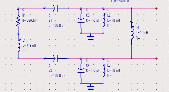
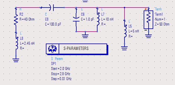
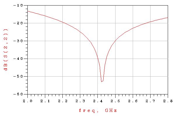
Could you mean the following match? Could you check it? The return loss is about -6dB@2.4GHz.
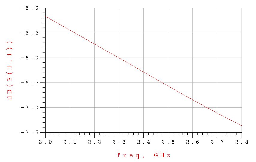
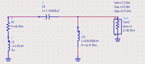
And I use smith chart to match, and get return loss is less than -20dB@2.4GHz. I think 2.4GHz is not so high, so I guess the theory match should have good performance in real match. Am I right?
Hi Tony,
It looks ok and will probably work very well. It is normally not hard to get these radios up and running.
If it is a hobby project, build it and be satisfied. If it is a more commercial product had I at least measured power and checked for harmonics.
Harmonics is a very common FCC problem with all CC25xx. Filtering can solve it but increases cost and board space and 1 dB loss.
Besides correct impedance match, design for good RF ground, also for the pad below the chip.
This chip is extremely complicated to impedance match if you want to match it for max performance without nasty harmonics.
I have spent many days to optimize balun and matching circuit for CC25xx. To get max performance must everything be measured. Component placement and PCB layout can affect a lot as also harmonic impedances (and their shorter wavelength) must be taken in account!
TI does not provide any information about this in application or data sheets, but they are aware about it. Taken from TI about CC2520:
The CC2520 is not only sensitive to changes in the impedance at the fundamental frequency but also at its harmonics, which is difficult to measure and accurately simulate.
Correct impedance matched harmonics, reduces harmonic levels by reflecting them back in the chip, but also increases fundamental frequency output level, difference can be several dB's.
CC2520 is known to be more tricky then CC2500.
TI CC25xx is maybe not worse then any other brand, all have some kind of issue, only wanted to share that these chips has given me some late nights.
Hi, E Kafeman,
Thank you very much.
Tony Liu
Load Differential Impedance 相关文章: