Quadrature oscillator

Dear sbinkhalid
Hi
I think the aim of those RC networks , is to provide enough phase shift . thus Av*beta can be around unit or greater , thus it can oscillate .
Best Wishes
Goldsmith
Hi
Thanx for your explanation but what i really wantd to know was what is the functionality of the resistors and capacitors and how differing their values will affect the output.
I think the fout =1/t*pi*R*C . thus you can select them . and their values are the same together .
And i think this file can help you more . see below , please :
oscillators.pdf
Good luck
Goldsmith
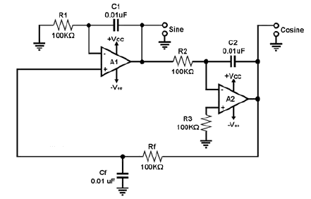
The shown oscillator circuit consists of two RC integrators connected in a closed loop.
It is a very versatile circuit that delivers two signals with a 90 deg phase difference.
The opamp circuit with R2, C2 is the classical inverting Miller integrator. The second opamp with R1, C1 together with the passive lowpass Rf, Cf form a non-inverting integrator stage (BTC integrator).
Thus, at the frequency w=1/RC (all RC elemets are equal) the loop gain magnitude is 0 dB and the loop phase is zero (90 deg. minus 90 deg). This fulfills the Barkhausen condition for oscillation.
An easy way to see the introduced phase shift of an oscillator is to break the loop, and see the phase shift introduced by the remain amplifier and phasing network (fed with similar signal).