RF transformer insertion loss
时间:04-06
整理:3721RD
点击:
Dear experts,
Say that I have designed a transformer in ADS Momentum which has two differential ports, namely, primary and secondary.
At the first glance it seems easy to find the insertion loss with evaluating the S21.
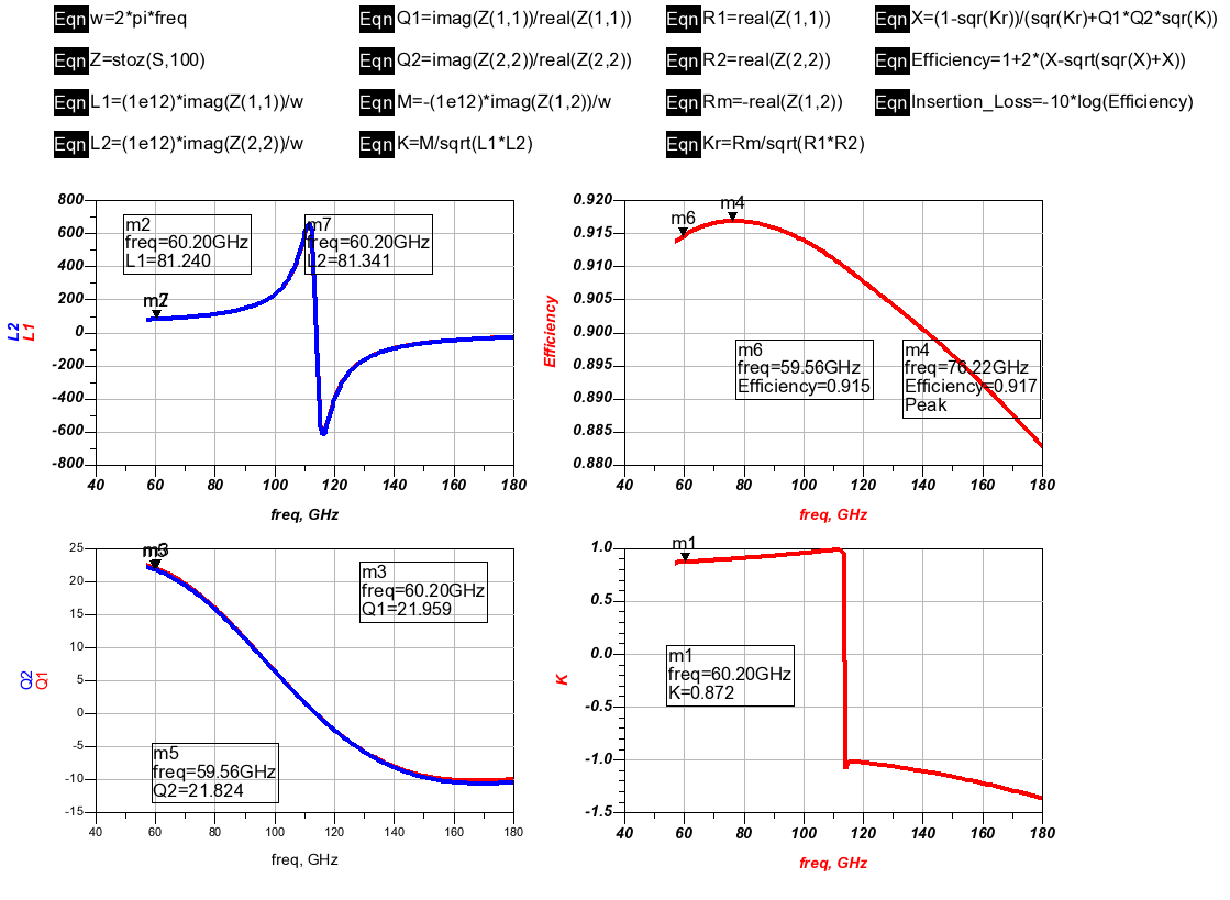
But in many papers that I will cite at the below "maximum available gain" is used as a figure-of-merit. This efficiency or maximum available gain can be found as:
efficiency= 1+2(X-sqrt(X^2 + X))
X= (1-Kr^2)/(Qp*Qs*K^2+Kr^2)
Kr= Rm/(Rp*Rs)
Rm=real(Z21) 2 is for secondary port and 1 is for primary port
Qp and Qs are quality factors of primary and secondary and K is coupling factor.
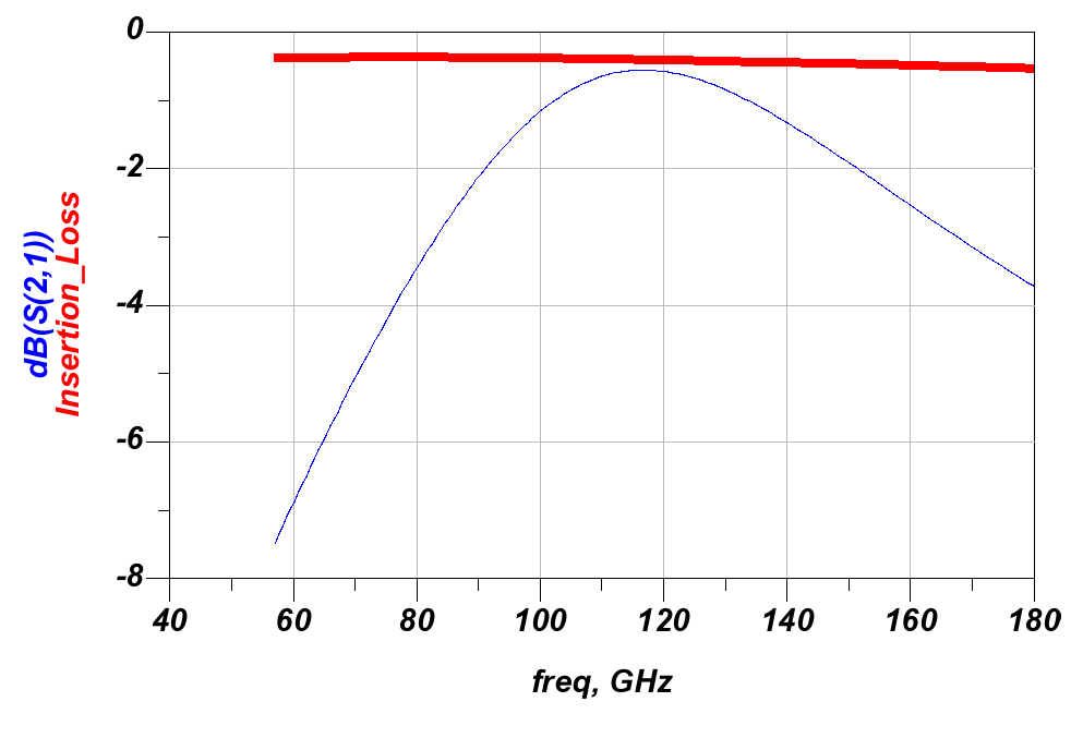
If insertion loss is calculated from this efficiency (IL=-10*log(efficiency)), it's way too different from S21 in dB.
This gets especially difficult if I want to design a network which has two differential primary ports and one differential secondary port.
What should I evaluate to find the insertion loss?
reference: K. T. Ng, B. Rejaei, and J. N. Burghartz, ?Substrate effects in monolithic RF transformers on silicon,? IEEE Trans. Microw. Theory Tech., vol. 50, no. 1, pp. 377?383, Jan. 2002.
Also you can see the results. Inserion_Loss is got with IL=10*log(efficiency) while efficiency is got from relations in the attached paper.
Impedance of differential ports are set to 100-ohm.
Say that I have designed a transformer in ADS Momentum which has two differential ports, namely, primary and secondary.
At the first glance it seems easy to find the insertion loss with evaluating the S21.
But in many papers that I will cite at the below "maximum available gain" is used as a figure-of-merit. This efficiency or maximum available gain can be found as:
efficiency= 1+2(X-sqrt(X^2 + X))
X= (1-Kr^2)/(Qp*Qs*K^2+Kr^2)
Kr= Rm/(Rp*Rs)
Rm=real(Z21) 2 is for secondary port and 1 is for primary port
Qp and Qs are quality factors of primary and secondary and K is coupling factor.
If insertion loss is calculated from this efficiency (IL=-10*log(efficiency)), it's way too different from S21 in dB.
This gets especially difficult if I want to design a network which has two differential primary ports and one differential secondary port.
What should I evaluate to find the insertion loss?
reference: K. T. Ng, B. Rejaei, and J. N. Burghartz, ?Substrate effects in monolithic RF transformers on silicon,? IEEE Trans. Microw. Theory Tech., vol. 50, no. 1, pp. 377?383, Jan. 2002.
If you post the paper which you have mentioned above and simulation results, we can comment about the subject.
Attached is the paper that I mentioned above.
Also you can see the results. Inserion_Loss is got with IL=10*log(efficiency) while efficiency is got from relations in the attached paper.
Impedance of differential ports are set to 100-ohm.
Found the answer
what is the answer?
transformer RF loss 相关文章:
- transformer S11 simulation
- Where Can I buy Transformer Core Ferrites for Frequencies ABOVE 200 MHz ?
- Can a transformer be used to convert single ended signal to differential signal?
- asking about quarter wavelength transformer?
- What is the best option to solve too wide quarterwave transformer problem?
- Transformer matching network design