clarification of a dipolantenna vertical/horizontal polarization via directivity plot
Basically what i would like to know is:
1) Is the polarization of a dipole antenna defined/based on the orientation of the dipole element?
or
2) Is the polarization defined/based on the orientation/direction of the radiating field?
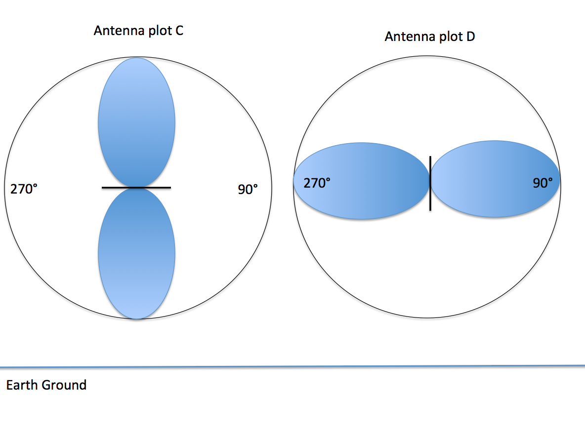
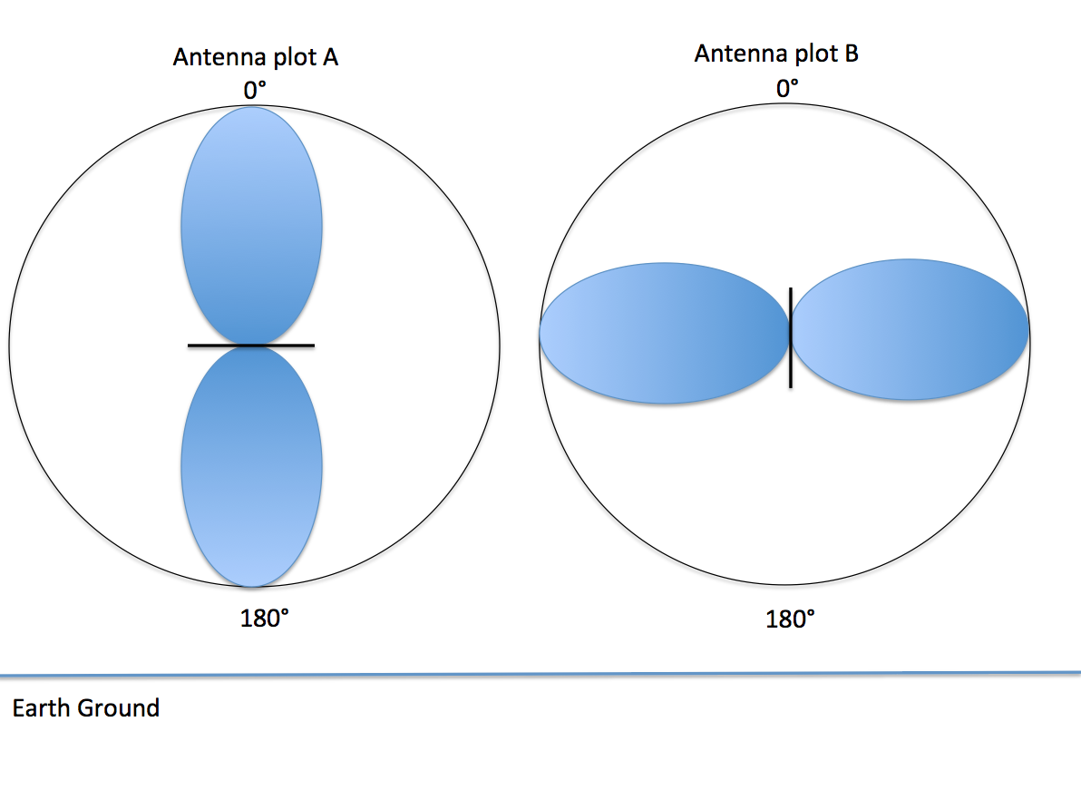
Please look at the attached images and tell me what defines E/vertical/elevation or H/horizontal/azimuth


The polarisation of a linearly polarised antennna is by definition the direction of the electric field. All 4 of your diagrams show E plane plots. You have not drawn any H plane plots, which would be circular for a dipole. Two of your dipoles (A and C) are horizontally polarised, the other two (B and D) are vertically polarised.
Knowing the radiation pattern does not in general tell you anything about the polarisation. About the only relationship I can think of is that if the radiation in some direction is 0, then there can't be any electric field, so there can't be any polarisation. Conversely, if you know everything about the electric field, you can calculate the radiation pattern.
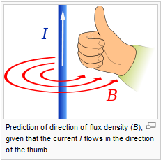
In the dipole, the current flows along the direction of the wire, accelerating and decelerating the free electrons, which create an E field parallel to the wire. The magentic field is at right angles, circling the wire. The ratio of electric field E (V/m) and and magnetic H (A/m) is given by |E|/|H|=Zo = 376.7 Ω, where Zo is the impedance of free space.

The direction of propogation in the far field is at right angles to both the electric and magnetic fields, which means it must be at right angles to the wire.
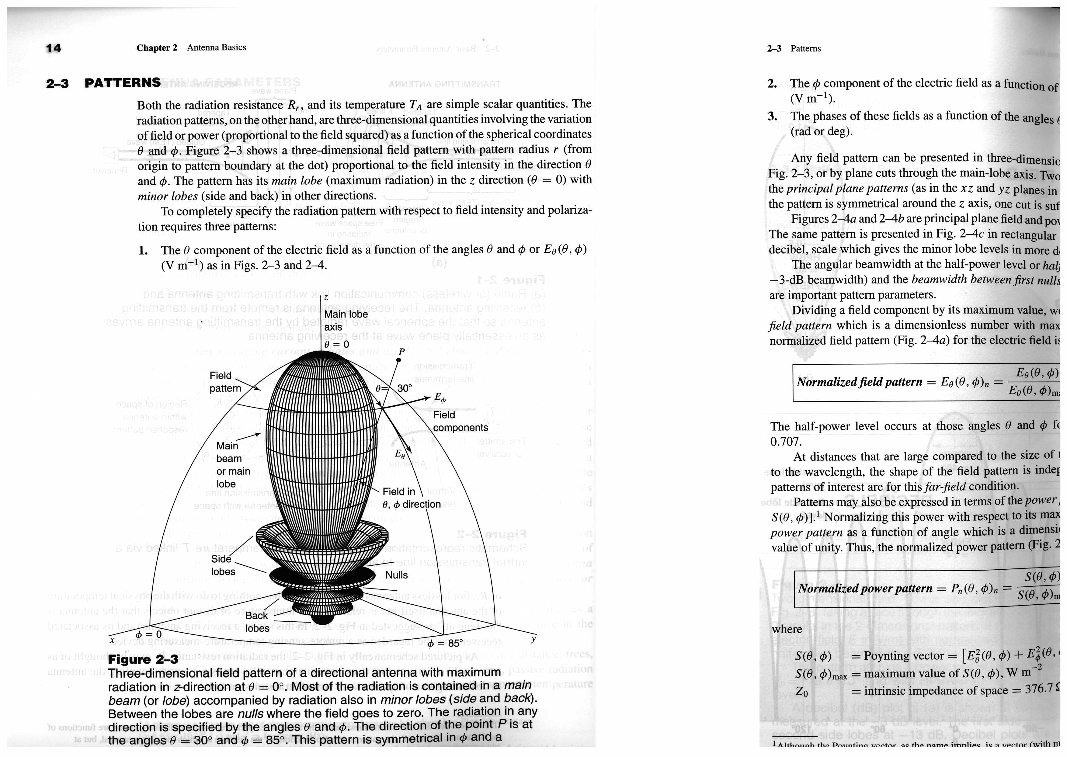
The following shows the normal coordinate system for an antenna, taken from the 3rd edition of "Antennas for All Applications" by Kraus et al.

Normally the directivity plots of antennas are shown as either a full 3D view, or of two 2D views at right angles to each other (the E and H planes). In the antenna shown, all the information could be shown on a singe 2D view, with D=f(Θ), as the directivity is independant of Φ.
As stated in Kraus, but not fully captured in my scan, you need 3 bits of information to fully describe the antenna.
1) EΘ (V/m) as a function of Θ and Φ
2) EΦ (V/m) as a function of Θ and Φ
3) The phases of both of the electric fields as a function of both Θ and Φ
Knowing the electric fields you can calculate the power density (W/m2) using the Poynting Vector. Knowing the power density, you can calculate the normalised radiation plot, but can"t calculate the gain. To calculate the gain, you need to know the power absorbed by the antenna too.
I hope that's some help, and I've not made any errors. Perhaps someone else can check over it.
Dave
For a H plane plot, can you tell me about the orientation/position of the dipole element. So for a H plane plot will the dipole element be vertical, horizontal in respects to the earth?
You can have the dipole any orientation you want with respect to the earth and still get an H plane plot. The planes relate to the antenna - not the earth.
There are 3 orthogonal ways to draw the dipole. Vertical (as you have done), horizontal (as you have done), and in/out the screen as you have not done. It is that orientation which will give you a circular H plane plot.
Look at the diagram showing the current on the wire, and the direction of B (the magnetic flux density in Tesla). Note how for a constant distance from the dipole, the magnitude of the vector B will be constant. That diagram could just as easily have B replaced by H, since they are related by B=μ0 μr H . Since for a given distance from the antenna, the magnitude of B is constant, the H plane for a dipole looks like a circle, just as in that diagram.
I hope that help clarify things, but if not, let me know.
Dave
Thanks for the support. Soon I hope I will have these antenna basics understood.
I see clearly the relationship between the H plane plot and the current on the wire diagram, and why the H plane plot is circular.
A few things are still unclear for me though.
You say that the drawings A and C are horizontally polarized. And that the polarisation of a linearly polarised antennna is by definition the direction of the electric field.
So based on that, the above text you wrote, my questions are:
1) Since A and C are horizontally polarized then that means by definition that the electric field is in the horizontal direction, correct? When I look at A and C I see a dipole that is orientated horizontally (to earth). Because the dipole is horizontal, the electric field points to 0 degrees(up/north) and 180 degrees (bottom/south). So if everything I said is correct doesnt that make A and C vertically polarized, because the electric field are vertical to the earth and vertical to the dipole?
You say that the drawings B and D are vertically polarized. And that the polarisation of a linearly polarised antennna is by definition the direction of the electric field.
So based on that, the above text you wrote, my questions are:
1) Since B and D are vertically polarized then that means by definition that the electric field is in the vertical direction, correct? When I look at B and D I see a dipole that is orientated vertically (to earth). Because the dipole is vertical, the electric field points to 90 degrees(right/east) and 270 degrees (left/west). So if everything I said is correct doesnt that make B and D horizontally polarized, because the electric field are horizontal to the earth and horizontal to the dipole?
Im not arguing that I am right. I am just exposing my misguided thought process hoping that you can help me correct it.
