How to tweak the Q of a 1/2 wave dipole antenna?
suppose my antenna is narrow band. How do I apply L and C circuit elements to make the antenna wider?
suppose my antenna is wide band. How do I apply L and C circuit elements to make the antenna narrower?
Is this a job for a smith chart?
For a dipole antenna the only thing that can affect the radiation bandwidth is the thickness of the two elements (thicker the elements, wider the bandwidth).
Making the return loss (VSWR) wider in bandwidth (using LC matching components), doesn't mean the radiation bandwidth will be wider.
Lower Q factor means more more bandwidth. To lower the Q factor, you have to increase the loss (ressitance). The ultimate in bandwidth is a resistor (Q=0) but that's also the worst in antenna performance.
ARRL Antenna Book said that
Q = fo*∆X / 2Ro*∆f
where fo = center frequency
∆X = change in reactance
∆f = change in frequency
Ro = fo resistance
This is why I initially thought that the Q of the antenna was impacted by applying L and C circuit elements.
A interesting case is the natural 0.5 lambda single wire dipole which have an impedance of about 72+j0 Ohm at resonance frequency. It makes the antenna a bit detuned in a 50 Ohm system. Often can impedance match be improved by adjusting antenna height above ground or minor adjustments on antenna structure. If tuning for minimum transmission loss is often other parts such as optimize lossy transmission lines or optimize SAW-filter and TX/RX impedance more important as 72 relative 50 Ohm only causes a minor loss.
If matched for a 50 Ohm system with LC components, it improves antenna efficiency at center frequency. By selecting LC components more or less good can resulting antenna radiation efficiency bandwidth be very different.
A practical test and measured result:
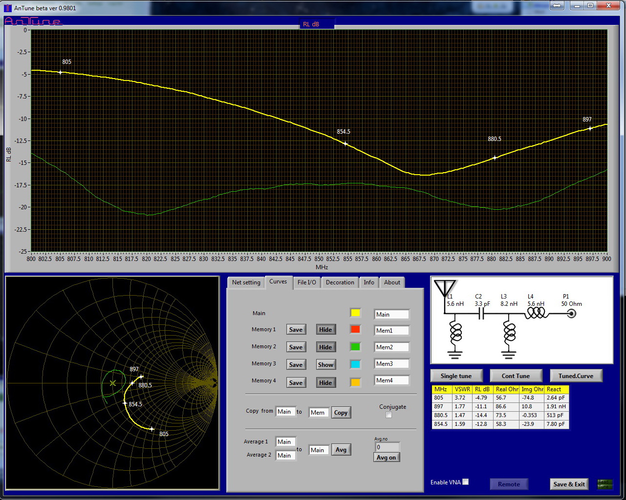
I did a simple wire dipole, resonance 880 MHz, measured impedance 73+j0 Ohm. See yellow curve below. Return loss bandwidth at -10 dB is about 65 MHz.
By adding the shown L/C network was return loss improved to green curve.
This matching network improves system efficiency over whole frequency range.

Same antenna and a single component matching network, tuned for max Q:

If we want to remain at 880 MHz as center frequency can the antenna dipoles be shortened a bit.
This kind of matching results in a more narrow band useable frequency range with minimal antenna efficiency improvement.
Selecting antenna Q and in this case correct matching network, is depending on want we want to achieve:
1. A widest possible antenna that is more resistant against detuning if environment varies.
2. A narrow band antenna that also improves out of band rejection, which can be equally important in some cases.
