Want help with dividing power among elements of phased array antenna

Interesting, i did not saw antennas with power dividers before. Only power divider for taking part of LO for comparansion with receiving signal in alarm system with combined microwave and infrared motion detector. Why are you using power divider in antenna, is there some benfits? About your problem, interested in explanation too.
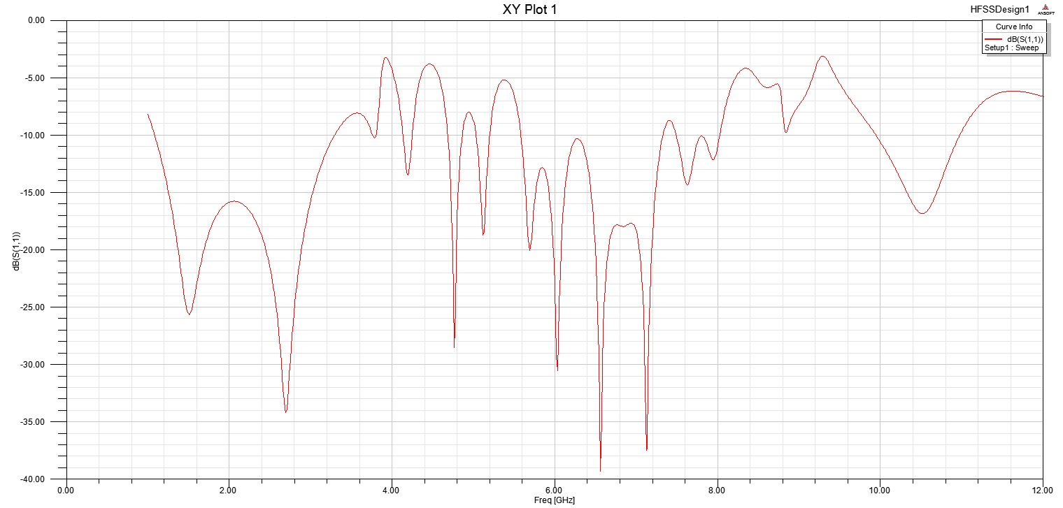
Actually the the power divider part is just the feeding network for my phased array antenna elements. I could not model the switched line network of phase shifting in HFSS ( because I am using skyworks rf switches for which I dont have s parameters matrix) so I directly connected the individual elements to the power divider just for checking the mismatches. These four elements are actually part of my array. I used wilkinson power divider because I intend to use this phased array for receiving as well. Please tell me what should I do to avoid resonance at other frequencies? Or they are just because of feeding network and wont matter for my antenna elements which are designed for 2.4 GHz. Thanks.
Terminator3 TV transmitters use many stages of power splitting to get the correct radiation pattern. if you take a horizontal dipole, it transmits power in the shape of a dough nut, so in the vertical direction the beam width is 360 degrees. if you stack 64 of them on top of each other, you can get the beam width down to one degree. You do this because there are not any TV sets vertically above the mast or at any angle above the mast. So half the power goes into this thin beam that touches the earth at a distance of typically 30 miles away and the other half of the power is used in a similar but different aerial to fill in the area from the mast base to this 30 mile radius. All these dipoles have to be fed through a power divider and a phasing line to get this complicated pattern.
Frank
i am not confident but may be with simulation in some equal band u get true result really i mean divide your band with to 3 band and simulated for example at 8-12 GHz it may be give u true result
Hi,I need help. I design and simulation with Ansoft Designer, a Wilkinson divider with a center frequency of 3.6 GHz and the characteristic impedance of 48 ohms ... I could describe the steps for the project, my first experience. Thank you in advance for your kind help and kindness.