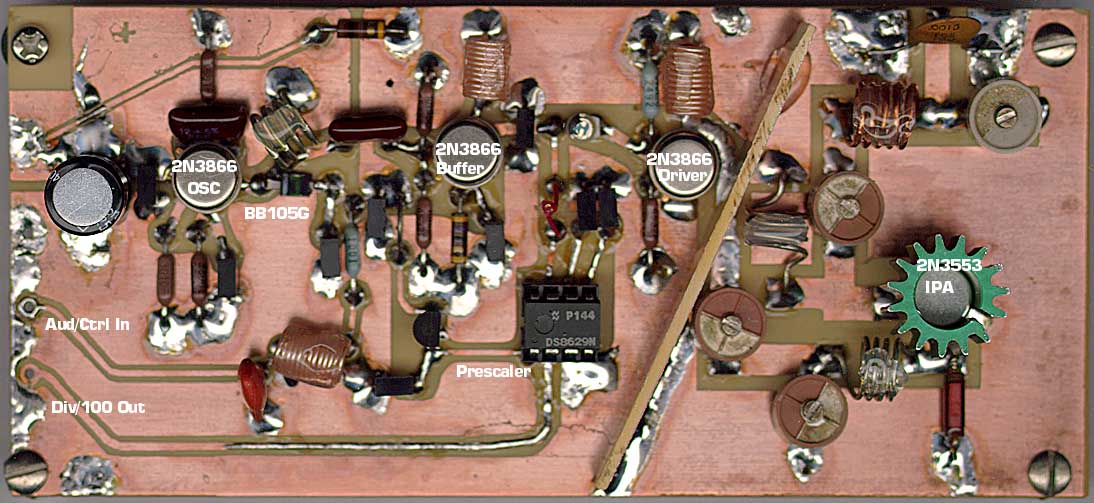
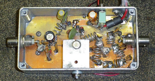
fm power amplifer problem !!!
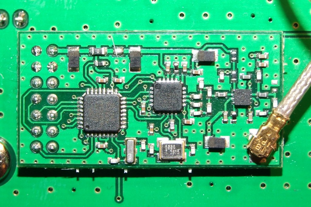
i ve upload the pic of the transmitter and the amplifer hoping any one would help me to make the fm stop transmitting and direct the o/p rf to the amplifer .
To stop your transmitter radiating you need to put it into a metal box with all the DC and audio leads bypassed with capacitors a tthey pass into the box. The aerial connection should be by a coaxial connector.
Frank
Hi tefavolc,
you have really only given us half your project and that makes it difficult to make any meaningful specific suggestions
but for some general important comments ....
1) ... how about a pic or 2 of the complete setup so we can see how you have connected the above shown board to your amplifier.
2) ... Building RF circuits on bread boards is a REALLY REALLY bad idea. You WILL end up with all sorts of problems you must build it on a properly laid out PCB so that you have some good control over stray inductances and capacitances. Else it is not going to work as planned
3) ... Chuckey also has given you some very important info and you MUST follow his suggestions. the bypass capacitors he is referring to ate called feedthrough capacitors.
anyway get some pics posted and we can go from there :)
cheers
Dave
i bought a new transmitter and the good news is that i found a node labled by ant and the bad news is that the same problem is still there the radio is receiving from the trasmitter not the amplifer . i ll upload a two photo , first for the new receiver and the sec is for the breadboard connection .
A RF circuit-whatever kind of-is NEVER implemented on breadboard.
yeah many told me that , but is there any other way to test it before making the pcb !
I think that your PA is oscillating, because is built on a breadboard with nor real RF grounding.
I'm embarrassed to say that I did something like this when I was an undergrad. It oscillated due to many reasons. Poor electrical connections and poor ground was definitely part of the problem. There was no pictures taken, lol.
tefavolc
OK its just not going to work for you. and if you are really serious about making this work, you MUST follow the advice given by Chuckey and myself earlier on.
AND
1) ... you MUST use a short length of coax between the initial transmitter and the power amplifier NOT some random length of unshielded wire ( its only going to act as an antenna for the original TX unit and radiate all on its own)
2) ... the 2 stages of the power amplifier CANNOT be side by side as you have done not unless its on a proper PCB and properly shielded
3) ... the whole 2 stage power amplifier MUST be on a properly laid out PCB or its never going to work.... for the reasons I gave in my first post ... about stray capacitance and inductance between tracks of ther breadboard
If you dont address these issues we will all be here for ever in a thread thats going to go round and round in circles without resolution
Dealing with RF is very different to audio circuits and without some reasonable knowledge and experience of what you are doing ... its not going to end well as you are discovering.
Dave
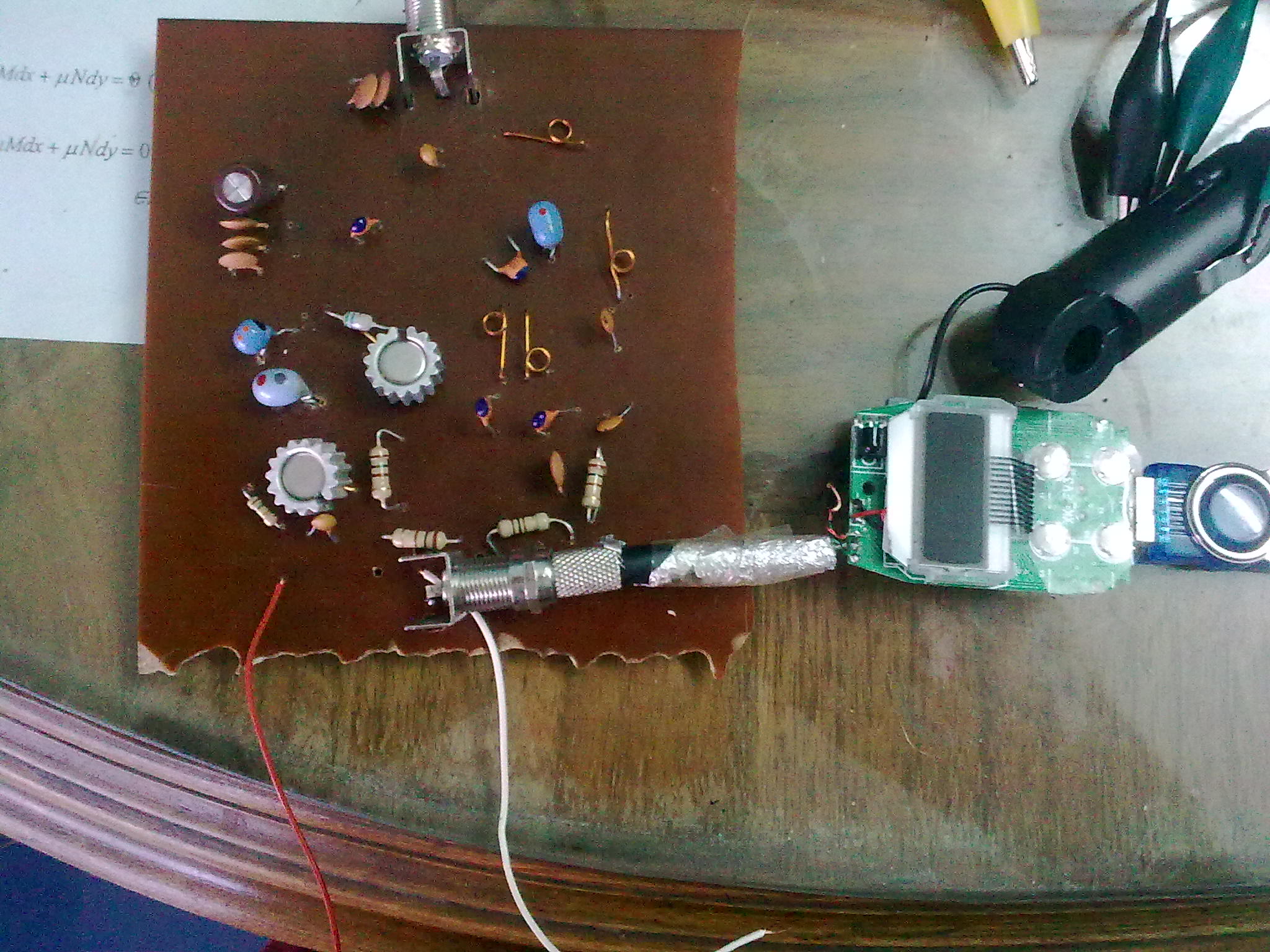
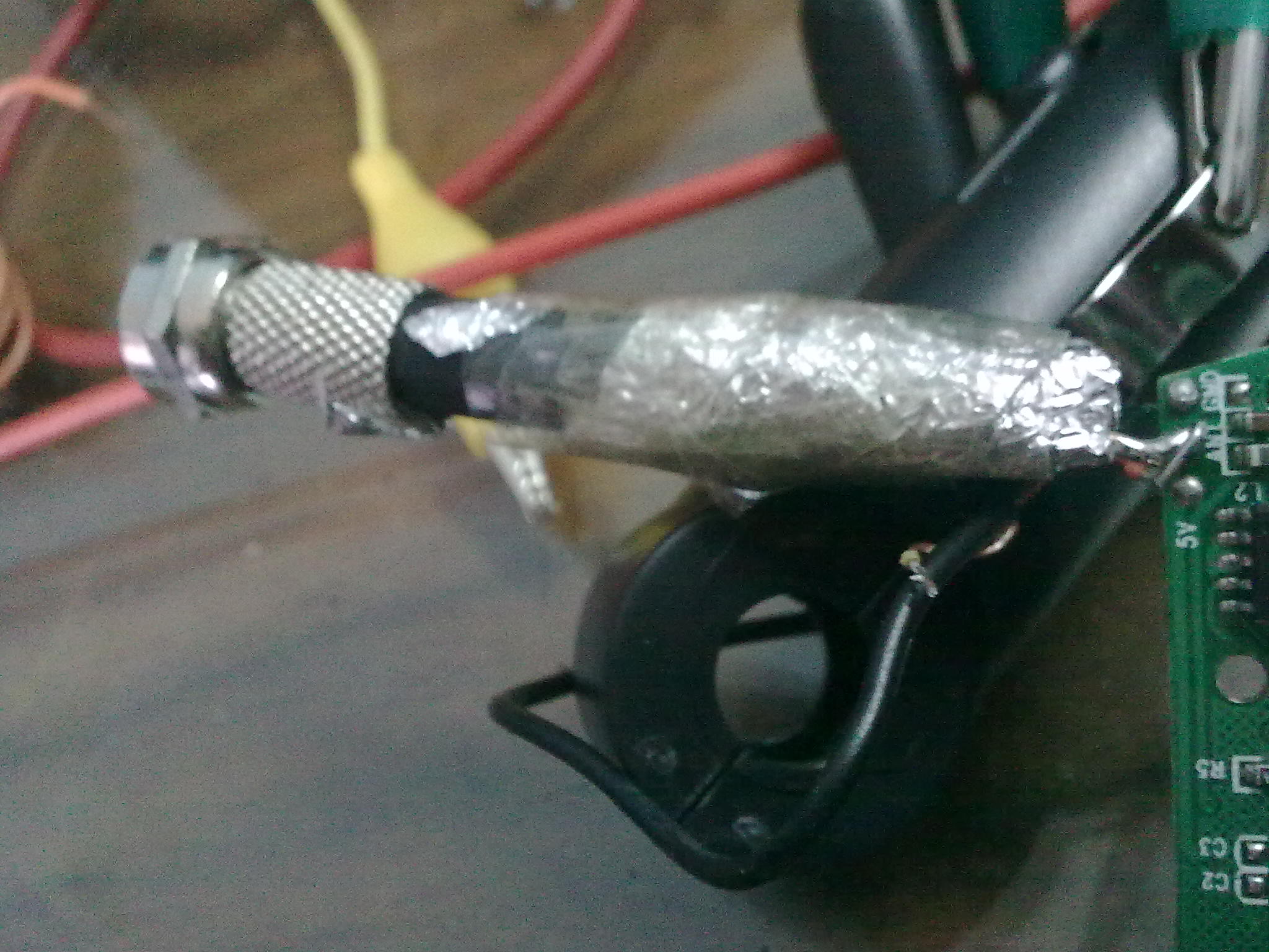
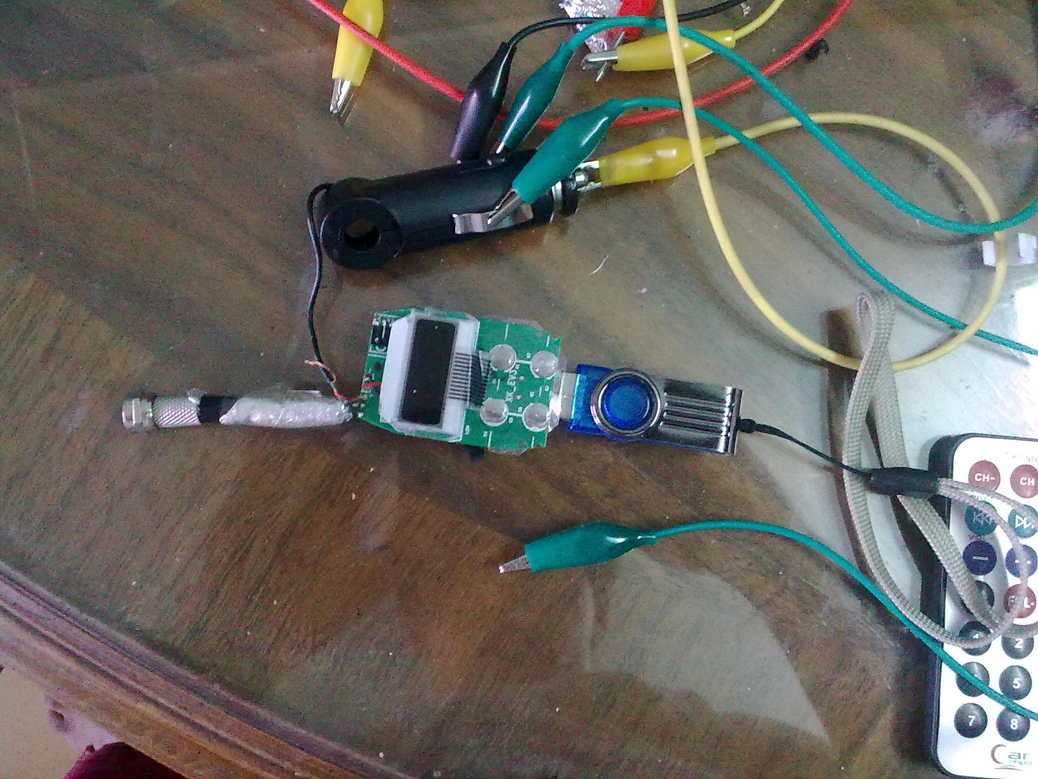
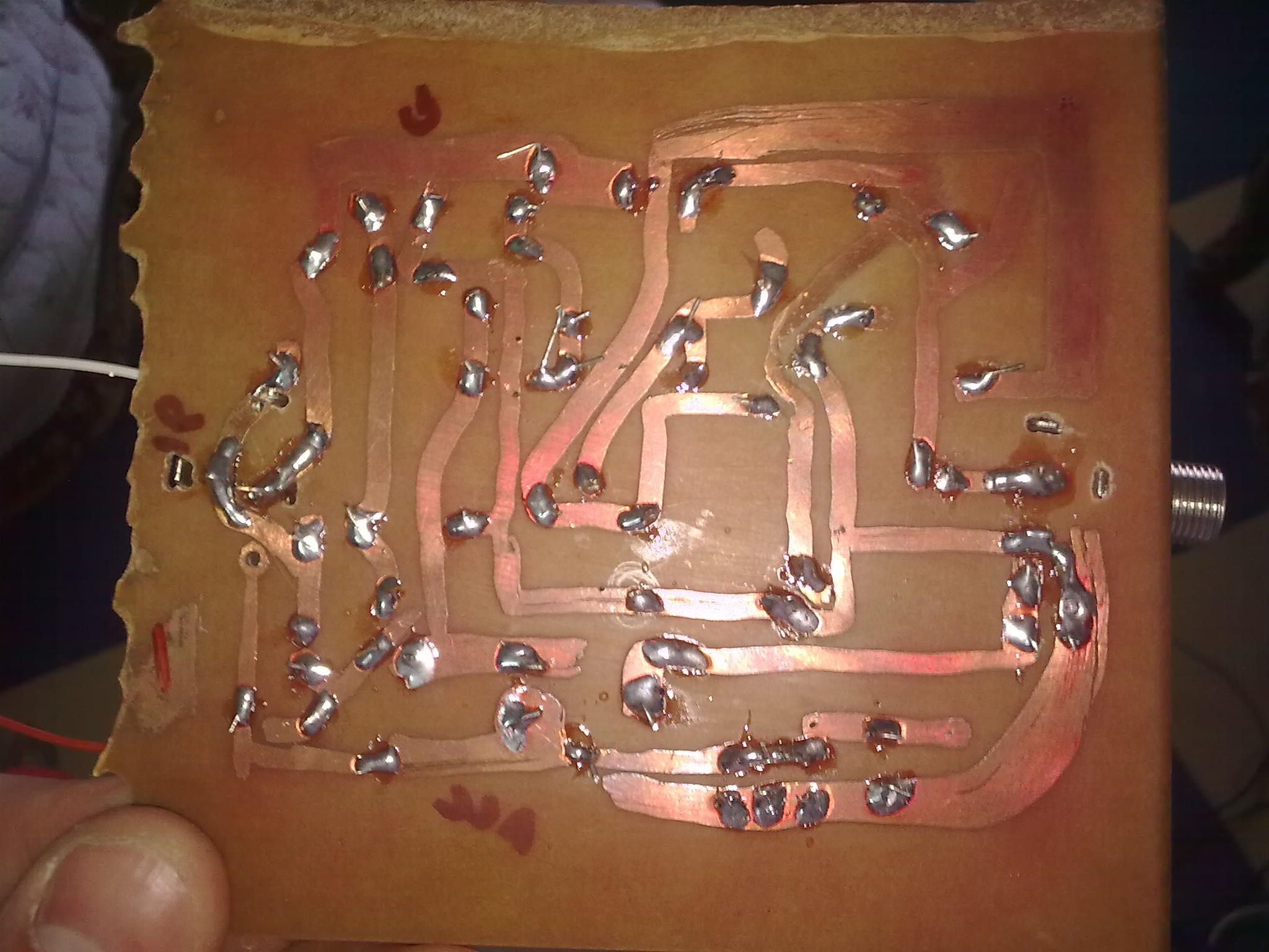
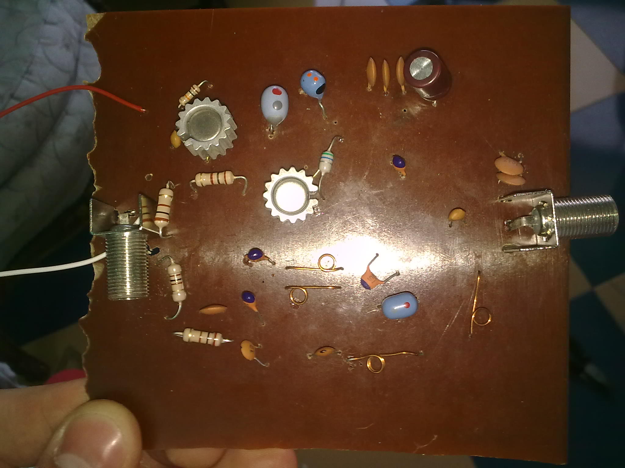
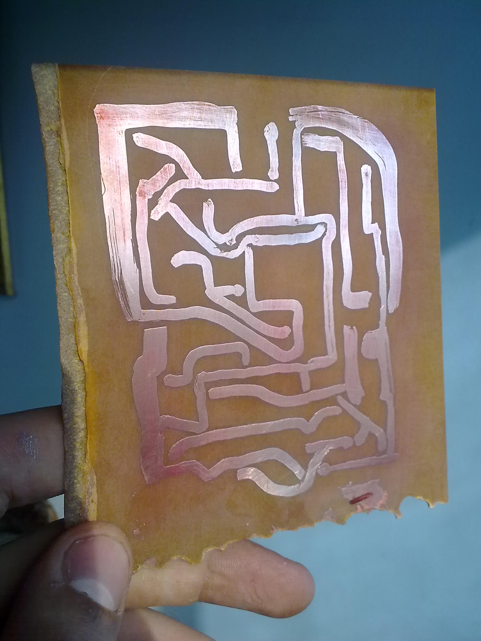
first thnx for replaying :) , and sory for being late , i was trying what i ve been told .
i implemented the circuit on pcb and coupled the transmitter and the PA by using short cox (rg-6) but unfortunately i still have the same problem , it seems that even a cox cable is still acting like antenna , although i have minimized the unshield cupper rode by extra AL paper thats also connected to ground .
i also tryed what chuckey said by putting the whole transmitter inside plastic bottle that is completely covered by grounded AL -paper and it also still transmitting :(
i ve uploaded some pic , and i hope that u help me as quick as possible as iam supposed to deliver that project in 2 days
You have implemented your circuit on a PCB WITHOUT ground..It wil not work properly.
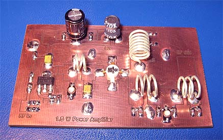
Instead, you must realize your circuit on a double sided PCB and second layer must be used as pure Ground so that every ground connection will be tied to single ground plane by VIAs.
Otherwise since the gropund currents can not return back to their sources and amplifier will obviously be oscillating.RF PCB design doesn't look like door ring pcbs.
thnx 4 replay
Good improvements, you is now half way to make it work.
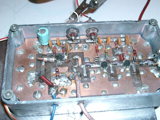
PA: Most critical problem that not will make it work is that there is no RF ground layer (See BigBoss comment, above). Ground layer is either a separate PCB layer or filling all unused space on existing layer or both with a lot of interconnections between these layers. Design for as much ground area as possible as it makes it simpler to get a RF circuit to work.
Se example:
Trace width and component layout is a part of the design, which affects if it will be any gain and tune-ability for a certain frequency. With a good ground I guess you could see some function anyway so it is not a too critical problem for now.
I had selected as less stiff and longer coaxial cable as it else add to much breaking force on PCB. Even a well shielded microphone cable can be good enough in this type of circuits.
RF ground connections are always as wide and short as possible, no pigtails as it looks lke between coaxial ground and main PCB.
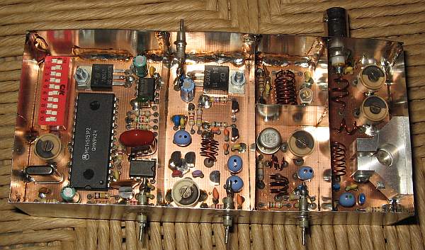
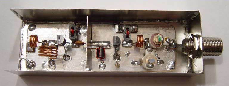
Flexible shielding can be done with CU tape or braid from a coaxial cable. Aluminum is almost impossible to use in hobby projects as it is hard to solder or connect in a way that is good enough from RF view. Both connection problem and soldering problem is due to the kind of oxide that always covers aluminum. Tin cans and PCB sheets can be used to build shielded boxes.
A shielded box is something where ALL wires not related to RF signal must be LF filtered against the metal box. Else will these cables act as antennas both inside and outside the box causing high leakage. RF cable shield must also be connected directly to the shield (no pigtails) .
Main board: Remove coaxial cable, verify that antenna connection point is connected to the RF chip, preferably in serial with a cap (DC decoupled) and not to any internal antenna. I have seen similar circuits that was using cigarette lighter + wire as an antenna. If so remove that circuit.
If needed add some PCB to support a good ground both for main board and coaxial cable ground. If I had done a similar project had I probably taken a big PCB and used as a common ground plane for both main board and PA, a bit like in attached photo.
thnx for replay :)
can i get other pcb and connect it tl the ground of my pcb ?
If you don?t have time to design a proper circuit, use a simple PCB/metal box/double side PCB box, e.g.
