Agilent high frequency probe HP85024A
"I am using high frequency probe to measure spectrum level on the spectrum analyzer. For accurate signal level measurement on the spectrum analyzer I would like to know the loss/contribution from this probe..but I am not sure how to take this ( or get the loss number) loss for a given frequency or a frequency range.
Can anyone comment please?
"
Setup:
SA freq @2.6GHz
Level=-43dBm [this level is measured with a HP probe on DUT]
what I want to know is:
-43dBm read out including a contribution from high frequency probe and how can extract this contribution or number added by the probe itself
If you know the answer please provide me a straight answer.
BR
MK28
The Agilent test and measurement forums are very helpful. I dont't know if this link will work, but give it a try.
http://www.home.agilent.com/owc_disc...?categoryID=23
Many of the people posting to the list are Agilent staff.
I'm assuming you have done the obvious thing and checked the manual. If not, download that. Manuals for most HP and Agilent kit is a free download.
Hi Freq Probes are not good for accurate measurements, Especially at higher freq.
You can take a measurement 5 times in a row and get fairly different results. Now
if you get some one else to take the same measurements it can be way off !
You can use it to get relative or "Delta" spectrum levels, but it will take a lot of
experimentation to get reliable methods of measuring.
Also Hi-Freq probes have capacitance built in. This capacitance can effect the
circuit if you touch it !
Yes, sometimes questions in return are the only way to find out which problem the poster is haunting(!)
The measurement error (or "contribution") introduced by the probe can be understood in different ways. There's a "straight" gain specification in the user manual which apparently doesn't answer your question. The problem may be that the specification doesn't include the effect of loading your circuit with the probe impedance. But that's just a guess because you didn't clearly tell. (see https://www.edaboard.com/thread268344.html)
Easy FvM...i sense sarcasm in your answer which is not needed. If you dont like the post then I suggest stop writing.
Why don't you make an calibration with a well known accurate signal source ?
@BigBoss: good point, actually I am working on it
Why? What FvM wrote is totally correct: you need to consider the loading effect of the probe impedance on our circuit.
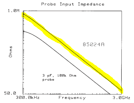
The loading impedance is shown in the datasheet: http://www.helmut-singer.de/pdf/hp85024a.pdf
As you can see, at 2GHz it is on the order of 100 Ohm, instead of 1MOhm DC resistance.

You did not mention the source impedance of your device under test, so that nobody can provide an exact answer what the loading effect (voltage divider!) will be.
You've started sarcasm in your previous thread, I'm still trying to be helpful.
To be honest, what I don't like very much is the demeanor showing in your complains about others posts...
By the way, I'm somehow under the impression, that the points brought up in this thread have been already adressed in my previous post.
- What is Real GND in high frequency IC design?
- how to get higher P1dB,in point
- How to increase high frequency output power
- Low and high impedance of low pass stepped impedance filter
- The power of standing wave is higher than that of standing wave
- Where can I place to get the high level signal? any explaination or reference?
