How to measure the current through the photodiode
For example, I am using a TIA to drive two photodiodes.
And I want to know how large of the current generated through each photodiode, and this measurement circuit will not have a effect on the TIA/photodiode pair.
I know there is some kind of TIA, which can measure the current, for example max3658. But I want know the current through certain photodiode.
thanks in advance.
I don't understand your post. A transimpedance amplifier doesn't "drive" a photodiode - it gives a voltage output which is proportional to the photocurrent. You will have to explain your problem more clearly to get help.
Keith
Hi, all
Flowing is my schematic. two photodiode connected the transimpedance amplifier (TIA) and then to the Limiting amplifier(LA).
I want to know how to measure the current through these photodiodes (I1 and I2)
If I choose MAX3658 as my TIA, which has a function measure the average current flow through the photodiodes , I can get the value of I. But I wan to how large is I1 and I2 separately.
what kind of circuit should I use ? a simple current mirror?
--------------------------------------------------------------------------------------------
OK, this time , I try to describe my question in detail.
First, I want to measure the current through the photodiode. Following is schematic.

two methods: 1 measure the output voltage of the TIA, and divided by the transimpedance gain. I= V/R.
2 use some TIA which has a function of "monitor the current", for example, max3658, which has a pin 4 called "mon". The current flow out this pin is always equal to the current flow through the photodiode.
Here comes my problems. Now , I am using two photodiodes connected to the same TIA, and I want to know how large is the current flow through each TIA., what kind of the circuit should I use to achieve this function? (Just like what MAX3658 do inside the chip)

Your diagram doesn't make any more sense than your description. Maybe it is because you have drawn the TIA backwards?
If so, then the output of the TIA will be the current multiplied by the transimpedance (18k in the case of the MAX3658).
As your circuit sums the currents there is no way to know which photodiode the current has come from unless you disconnect one, or use a circuit which connects individually to each photodiode with a TIA and then sums. Or maybe add a multiplexer to selectively disconnect each one in turn.
Keith.
Hi keith, I just describe my question in detail. hopefully it is clear this time.
The MAX3658 MON pin provides the average photodiode current from it's DC current cancellation circuit. This is a circuit that takes the output from the transmittance amplifier and filters it and feeds it back to a current source at the input.
I think if you need to monitor the current (either at high frequency or low) from each photodiode you need to split them somewhere. I would suggest two transimpedance amplifiers and then sum the outputs of those.
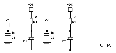
If you ran the photodiodes with a reverse bias voltage (I am not sure if makes sense to run them at zero bias anyway) then the average current could be monitored with a resistor/capacitor as below.

If you want to monitor the current of each diode at speed then I think you need two TIAs. If you were to try to use current mirrors they are unlikely to be quick enough. Also, I would be surprised if adding any active components didn"t introduce noise.
Keith
measure photodiode 相关文章:
- How do I know if a spectrum analyzer is enough to measure an specficic DAC?
- Using ADS2019, How to set and measure tempature values for LNA?
- H field measurements with waveguide twist
- How can I measure the Side-Band Amplitude?
- Keysight PNA Harmonics measurements
- frequency shift between simulation and measurements
