IE3D:What is the Terminating Impedance Zc?
I am going to design a antenna to match the chip impedance with 22-196j.
What is the Terminating Impedance Zc i need to set?
Terminating Impedance mean load impedance when calculate S11(Gamma)?
From the equation Gamma = (Zc-Zo)/(Zc+Zo),
where Zc = load impedance = terminating impedance?
Zo = source/chip impedance
So the terminating impedance = 22-195j to achieve Gamma to zero.
Am i correct?
I quite don't get what you are actually asking... however as a general rule in RF we terminate with 50 ohm or 75 ohm impedance
Hi smoothcriminal,
Thanks for your reply and sorry about the clearness of the question.
Now i am going to design a RFID antenna and match the chip impedance which is 22-196j
In IE3D , i want to obtain the S11 graph after simulation.
What should i set in terminating impedance Zc?
I can sure it shouldn't be 50 or 70 ohm.
Should it set to 22-195J or 22+195J?
Correct me if it is wrong.
Thanks so much=)
ok what i understand is that you want to match the source impedance to load impedance (22-196j) and you are confused whether to use 22-196j or 22+196j as terminating impedance!
the ans is you use "complex conjugate" of the impedance that the load is offering .. in your case load is offering 22-196j so you will use 22+196j as terminating impedance ... and match it to source impedance... you can verify it through s11 graph ! more negative amplitude in db means less relection back!
22+195J IF you put the antenna right at the output terminal(s) of the chip. If there is a transmission line inbetween the antenna and IC, then you need to make the antenna match to a very different impedance!
Thanks for your reply again =)
1)I am confusing about the source impedance and load impedance.
In this case ,
source impedance = chip impedance (22-196j) ?
load impedance = antenna impedance( 22+196j) ?
And i agree with "the ans is you use "complex conjugate" of the impedance that the load is offering"
I think terminating impedance = 22-196j
Correct me if i am wrong.Thanks all.

As you said (which you should have specified before)
source impedance = chip impedance (22-196j)
load impedance = antenna impedance( 22+196j)
we all know Zl=Zs* , which means if your load is equal to complex conjugate of your source, which is in your case as you say source is (22-196j) and load is (22+196j) then max power will travel...
This is my summarize.Am i right about the understanding of terminating impedance?
Given: chip impedance = 22-196j
Below is my approach,
Step1) design a pattern on patch antenna to obtain a Z-parameter graph
which (ideal case : antenna impedance = 22+ 195j between 860 to 940MHz)
Step2) input terminating impedance to calculate S11
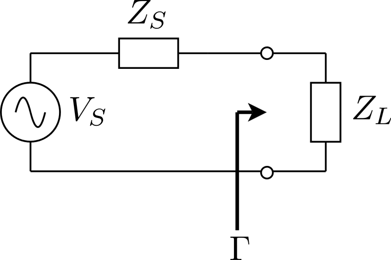
reflection coefficient = (Zload - Zsource)/(Zload + Zsource) < -10db
( circuit diagram is attached)

Zload = antenna impedance (22+195j)
Zsource = chip impedance (22-195)
terminating impedance is the "complex conjugate" of the impedance that the load is offering
So terminating impedance = 22-195j
Thanks.
