why my sp analysis always plots the same S11 and S21 curve for me?
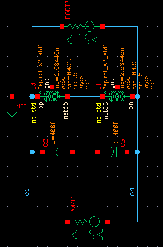
I schematized a LC tank and connected it with an input PORT0 and output PORT1 and then I do a sp analysis. But no matter how I change the value of L or C, always plots the same S11 and S21 curve.
What's wrong? I just want to extract the sparam of the tank.
Hope someone can help me.
Have fun,
Justin
effectively, S11 and S21 must be differents. Could you give a snapshot of your SS and S21 curves please ?
I'm looking at the capacitor values. They are labelled 400f.
At first I thought it could be 400 Farads.
But then I looked at the coil units and I see they are 'n' for nano.
So could the capacitors be 400 femto-Farads?
What resonant frequency were you aiming for?
No matter the values of capacitors and inductors, S11 and S21 must be differents.
In pass band , for a trap circuit, S21=1 and S11=0 idealy. Out of the passband S21=0 and S11=1. So S11 must be different to S21, isn't it ?

You may misunderstand what I encountered. I mean no matter how I change the value of ind and cap, S11/S21 always kept the same.
I set L1,2=2.5nH, C1,2=400fF, it is just as the photo I send to you.
I then set L1,2 another value, it is still the same curve.
I am confused now. What do you think of this?
Thank you!
- - - Updated - - -
Hi, Brad
I just design a 5GHz oscillator. I think it is normal values. What do you mean?
Thank you!
- - - Updated - - -
FYI. Thank you very much.
Checking the resonant frequency...
Your schematic has two capacitors in series. Each 400 femto-Farads. Their effective value is the reciprocal of the sum of the the reciprocals. Net result is 200 fF.
The two series inductors are added. Net 5 nH.
Taking 1 / ( 2 * Pi * SQRT ( L * C ) )... 5 GHz as you stated.
The scale between the coil and capacitor values is 25,000. To bring out resonant action, your tank loop ought to be operated at lower current, higher impedance. (If the spread were smaller then it would be associated with higher current, lower impedance).
You installed resistors at the incoming/outgoing locations. Their values are not marked. Try experimenting with those resistor values.
I believe you will observe the most pronounced performance when the ohmic resistance is the same as the inductive impedance and capacitive impedance, at 5 GHz.
@ustligen1,
My reply was for Bradtherad,
I don't misunderstand what you said. Are you agree with me if i say that no matter the values of inductors or capacitors (it's what you say before)?
When you sweep the frequency (even if you are not at the resonant frequency) , S11 must be different from S21.
Consequently the reply of Brad don't answer to your problem : why S11=S21 ?
However i haven 't the answer too.
Dear Brad,
I just want to use the Sparam to calc the actual ind value and paralell res. Do you have other ways to measure them?
Justin
Ok, i apologize. I have understand your problem now.
First question : when you change the value of the inductor and capacitor, do you change them at the same time because if your product LC is constant, the resonnant frequency is also constant too ( i don't think so that you do that).
Use S parameter is appropriate. In ADS software , this sort of simulation is not difficult to do.
Sorry, I'm not sufficiently familiar with the S11 & S21 terminology, and methods to measure them.
I'm not sufficiently familiar with a simulator that can do that.
The simulator I use makes it easy to set up several LC tank loops (all identical), with different input resistors, and to apply a frequency sweep, and display scope traces. Simultaneously on screen.
This screenshot shows the effects of various input resistor values.

The coil value is 25,000 times the capacitor value (as in the OP schematic).
Notice the effects are obvious. There is a particular range of input resistance which brings out LC tank action.
If input resistance is too low, the LC tank has little filtering effect.
Too high and the LC tank attenuates the signal and acts less as a filter.
I don"t know for sure whether this implacts S11 & S21 results. It's just my effort to contribute in a helpful manner.
Thank you for your help.
Actually, I made a very stupid mistake as I shouldn't add any res value to the port because the parasitic res of the spiral ind is about 1e3~1e4 order of magnitude. So if I add a 50 ohm in the output port, 50 ohm paralleling with what I actually desired R_ind will with no doubt destroy it.
After I cancel the res val setup and make it default. Everything works well. What I extract from sp analysis such as 'Q = IM{Z11}/Re{Z11}' and so on perfectly coincides with experienced values from textbooks.
Thank you again for your time.
Justin
- - - Updated - - -
Thank you for your information. It really helps. I am just not that much familiar with cadence tools.
50 ohm matching makes no sense in my case and you are right. I now extract the desired params from sp analysis. What you said is important after I put the tank into the system.
Thanks!
Justin