how to choose R C value in a rf Signal amplitude detect circuit
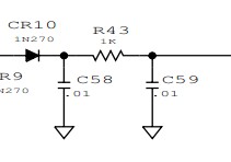
i know how to choose C58 by this
C*RL(Generally50Ω)≧(3~5)T/2
i use software to Simulation,find when r43 is changed,amplitude of V is changed ,but how to decide r43 and c59
What are the carrier and modulated frequency values
They depend on the desired demodulation bandwidth and output loading impedance. The 0.01 uF cap after the diode will also impact bandwidth of demodulated signal based on driving impedance and diode resistance.
just a 10MHz signal,and detect its amplitude
You'd better simulate the circuit in ADS, then you can adjust the components to any values, and see the effect on the power detection.
actually i did it ,when rf amplitude is constant,R value influence output value(voltage),but i dont know if it is the reason that R is here,and how to chose R 's value
After the power detector, if you connect to a OpAmp, the series resistor is always 1K~10K.
And, normaly, there should be a big resistor, say 100K, from the detector output to GND.
Thank you for your patience to answer