vco control voltage in pll behavioral simulation in simulink
时间:04-06
整理:3721RD
点击:
Hi,
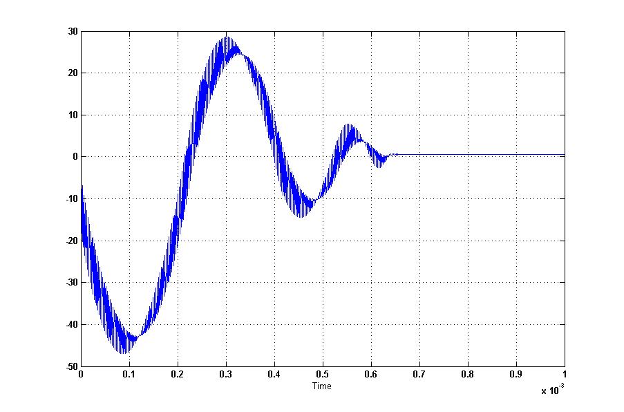
i simulated my pll using simulink n time domain and ended up with peculiar control voltage even with 60 deg/75deg PM.
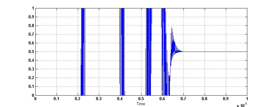
Fig 1 shows the output of loop filter. Fig. 2 shows output after VDD saturation. I want my vco control voltage to slightly rise from 0 at t=0 and settle as if critically damped.
Is it due very small ref frequency and high N=2500
fref=400khz fout=1Ghz N=2500
i simulated my pll using simulink n time domain and ended up with peculiar control voltage even with 60 deg/75deg PM.
Fig 1 shows the output of loop filter. Fig. 2 shows output after VDD saturation. I want my vco control voltage to slightly rise from 0 at t=0 and settle as if critically damped.
Is it due very small ref frequency and high N=2500
fref=400khz fout=1Ghz N=2500
It depends upon your loop filter's dynamics. Loop bandwidth phase margin etc.Check with that.
I checked Phase margin and I get similar response even with 75 degree PM
Maybe you can try 45 degree
- Induced voltages on transmission line by plane wave in HFSS
- Klystron output voltage, cavity field strength
- Negative voltage needed in K-band
- How to set the bias voltage of the BJT in Gilbert mixer
- is DC voltage gain not an important issue to consider in LNA designing?
- Power (Voltage / Current) inducted in rectangle antenna.