50 Ohm Wave Terminates in Purely Reactive Load
If so, this would greatly increase the voltage across the load being:
P=V2/R
Are you trying to remove resonance from the circuit?
you may use resistance having less power dissipation; I think so it will help you
No, I'm not trying to remove resonance. I just need to know how the energy of the wave propagating around a 50 ohm load translates into e.g. an antenna; which has no real impedance but is reactivley matched.
No real impedance => no radiation. If it not radiates is it a rather useless antenna.
If the load were purely reactive, S11 would be 1. Since it is near zero, the load impedance is obviously 50 ohms with no reactive part. And yes, if this is a resonant circuit, the voltage across this load will be much higher than you would normally see.
Referring to this diagram:
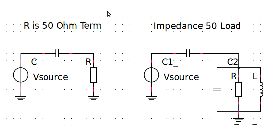
So the voltage across C2 would be much larger than the voltage across C in series? Is there a theory I can to refer for this?
Your diagram is opposite to a purely reactive load, at resonance frequency. Reactance X is then infinite and total load impedance Z is: 1/R + 1/X = 1/Z => R=Z , a purely resistive load.
First sentence is at least possible and reactive load is almost none. Second sentence is the opposite, now is it a purely reactive load, but it is not is possible to reactivly match something that have no real impedance to become a matched real load in a 50 Ohm system.
Theory is: Z=R+jX
What ever you do with X, if R is none from beginning, it will remain that way as long as it only is pure reactive matching.
In your diagram on the right side "impedance 50 ohm", the L and C2 tell where in frequency a resonance will occur. As stated above at resonance, the Yl and Yc susceptances will cancel out, since at that one frequency Yl = - Yc. That means all you have left are the coupling capacitor C1 and the equivalent R. You can vary both to get just about any |S11| you want.
Thanks for the variation of explanations.
So is it safe to to say: when Yl or Yc begin to drift (due to heat, climate change or environmental reasons) then the total impedance is changed which causes a mismatch in the system?