Power detector with schottky diode design
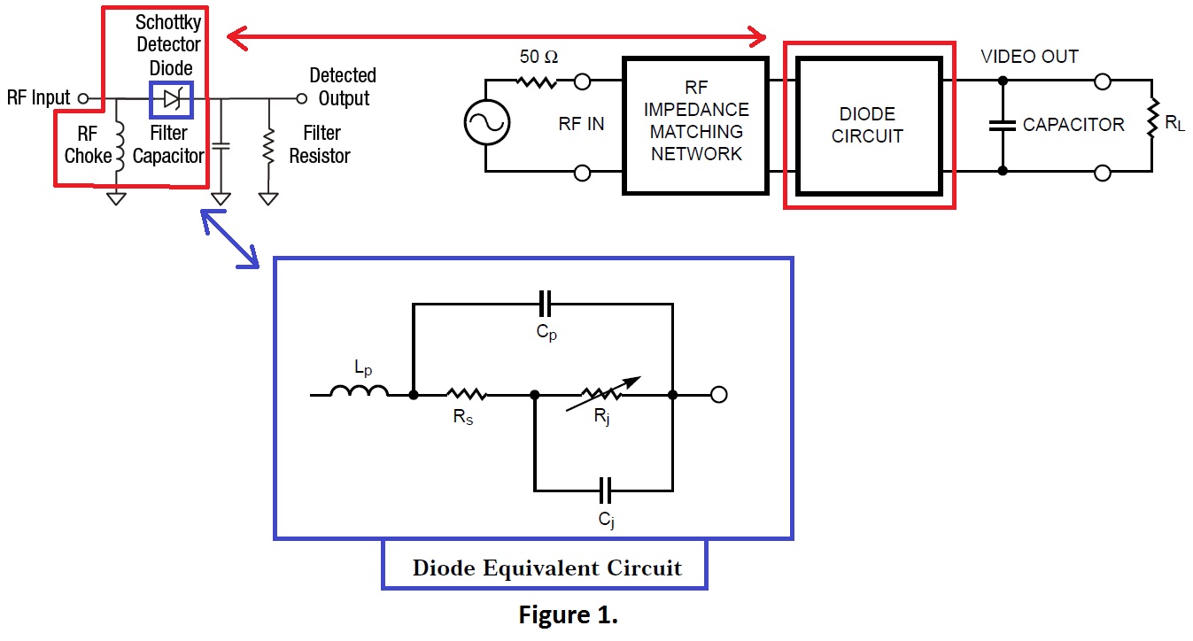
I'm trying to build a power detector with schottky diode shown on figure 1.

I', really new at this, I heard that because of diode C and L the detector won't work at all frequencies and therefore we must add a matching network.
Correct me if I'm wrong.
I'm trying to understand how this works and how to made a network for the power detector at frequencies from 150 kHz to 1 GHz?
I will appreciate if someone give me a hint or where to start with this problem.
Thanks :)
Cp and Lp ? . Most RF power stuff is matched into a 50 ohm impedance, which is missing. At low frequencies, providing that the DC load on the diode is high, the impedance of the detector can be ignored. At high frequencies (> 100 MHZ) the standard of construction (coaxial circuits) will have the next big effect up to 1GHZ? Then the diode losses will have to be taken into account. if you build a matching section, you are automatically reducing the bandwidth of the detector. Its best to make it wide band and have a calibration chart to compensate for SHF use.
Frank
Thanks chuckey.
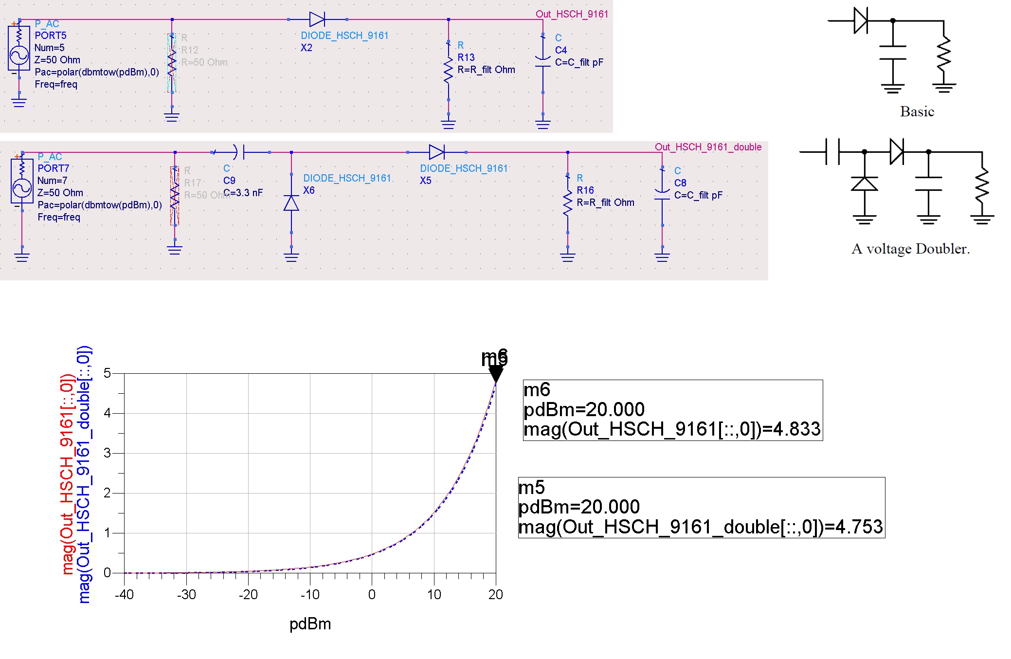
I'm now trying to simulate a voltage doubler circuit but I get the same result , see attached figure.

What am I doing wrong?
hope this thread will be useful to you
https://www.edaboard.com/thread278598.html#post1194660
- - - Updated - - -
I made the power detector mentioned in the thread and it works well!
detects up to about -30 dBm power input...
