how to measure a varactor using a VNA
I'm working on measuring a varactor(Toshiba 1SV287FCT-ND) by using a VNA.
I need to know the V-C and V-R character when operating at 2.4GHz.
Can someone give me some details about the measurement?
Many thanks.
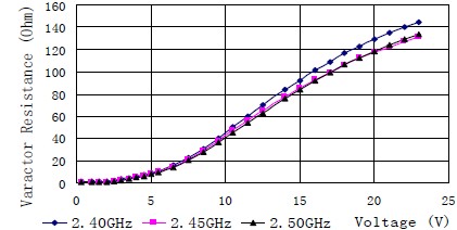
Here attached a sample figure.

You must first design a test fixture for the varactor, and characterize it in open and closed state. The jig must have the provision for DC bias as needed. The varactor will differ from the empty jig by its complex impedance, from which you can derive the variable capacitance.
one way would be to hook It up in parallel to a 50 ohm line, with a known high q resonating inductor in shunt across it, and high Q series caps to limit the coupling. Then I would vary the voltage and record the resonant frequency, 3 dB points, and loss at the mid point of the resonance. From that I can determine the R and C as it would be used in a real circuit
Note that the calibration is very important.Because few pF capacitance values can not be measured without a good calibration.
The calibration must be done after all parasitic effects have been taken into account such as bias tee, DC blocking capacitors,transmission lines and also soldering pads etc.
And don't overdrive it with too high an RF level from VNA, particularly at low reverse bias levels.
- How do I know if a spectrum analyzer is enough to measure an specficic DAC?
- Using ADS2019, How to set and measure tempature values for LNA?
- H field measurements with waveguide twist
- How can I measure the Side-Band Amplitude?
- Keysight PNA Harmonics measurements
- frequency shift between simulation and measurements
