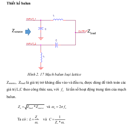
Microstrip Balun Design using ADS
I am designing a microstrip balun and plan to do it by using a Wilkinson divider to divide the signal into 2 signals with equal amplitude and then a Lange coupler to obtain 90 degree phase shift between the signals. The problem is with this design I am getting S(2,1) and S(3,1) more than -3 dB. What can be done to rectify this and bring S(2,1) and S(3,1) within -3 dB limits?
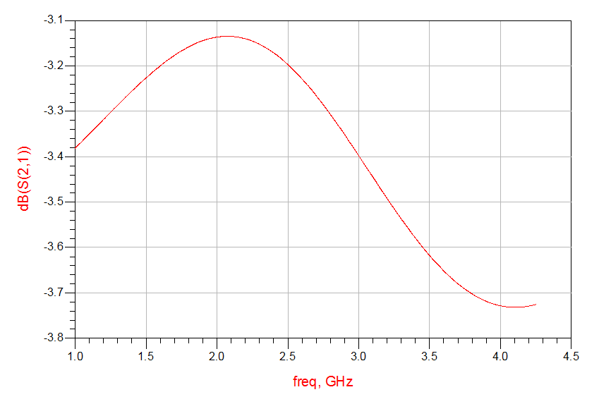
Here is a screen shot of S(2,1) that I am getting. Please help!
90 degrees?
Its -90 deg and +90 deg...so 180 deg phase shift between the signals.
a lange coupler is 0/90 degrees, not -90/90. so the combination would not make up a "balun"
Yes! That is what I meant. We have 2 lange couplers in the design. One lange coupler gives -90 deg phase shift to one of the signals and 90 deg to the 2nd signal and together they make up 180 phase shift between them.
-3dB loss is the theoritical value of Wilkinson Power Divider.In practice this loss will be a bit higher than this as same as you found.It's normal..
well if u are going to go to the trouble of using a splitter and two lange couplers....why not just make a balun in one piece: Marchand balun, lumped element balun, or if low enough frequency, a transformer from mini circuits, or even a splitter with a 180 degree line length on one output (possibly a shiffman section)?
With all those parts in the way, it will be hard for them to work in real world like a simulation might say they will, VSWR intractons and phase imballances
I have designed a marchand balun with broad coupled strip lines which works perfectly fine but I want to use coupled microstrip lines in the design. Any idea how to transform the circuit below to use coupled microstrip lines?

hi Ashwini Kundur.
the balun has many types depening on my design. you can read document.Balun Design.pdfBalun_Report_Preeti_Vijay_new copy.pdf
The balun you have designed in the second attachment has S(2,1) and S(3,1) at -16 dB. Will it even transmit any signal at these values? I want S(2,1) and S(3,1) at -3 dB. Here is the design of the circuit I have done. Can anyone please tell me where I am going wrong?
i don't design the balun in the second attachment, that is a document reference. S(2,1) and S(3,1) at -16 dB, it has -16dB transmitted.
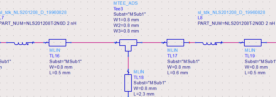
i saw your design, you should add MTEE, M-Line for the design to like in the fact.
Resistors, capacitor, inductor you used like in the fact, the ADS has support library of supplier.
with shape of your design, you should check to ensure.
The attachment you have posted is not viewable. Can you please post it again. Thanks!
it should be sth like the attachment, but i don't optimize the value.
you should optimize it.
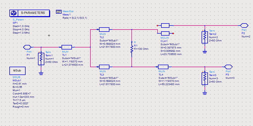
I optimized one power divider for you. And the performance charts. I think that's OK.
I am curious about why you want to use MLANG? Do you just need 180 degree difference in phase between port2 and port3?
Why not use microstrip length difference to do so?
Yes I need 180 deg phase shift between the signals at port 2 and port 3. I also tried using a microstrip line(coupled) to do so. Here is the circuit for it. Can you please help me out in optimizing this?
Coupled line seem can OK, I am optimzing it for you, but you can try first, don't rely on me, I am a little busy in work.
it can divide into two step, first designa power divider, which I have done it for you.
The second is find an idea can cause 180 deg phase diff.
Can anyone tell me how to optimize values for MSTEP, MTAPER, MTEE and other such design elements. Is it a trial and error method or is there a specific way to design for these like the linecalculator we have for other elements?
That value is following the trace width values, not independent.
Can you tell me what is your specifications for freq band? 1G-4G is too wide.
AWR has some examples to design phase shifter, and MEMS pahse shifter can achieve 3G bandwidths in mm band.
ANd youc an also use some hybrid to shift the phase about 180 degree, Mini-Circuits has such ICs, but you need divide the freq bands,
The center frequency is 2.14 GHz.
What's the bandwidth?