About the parameter of class E power amplifier design
时间:04-05
整理:3721RD
点击:
Dear all,
Have anyone ever used this tutorial widget of class E amplifier design?
(you can get it easy by google the keyword "tonnesoftware")
I don't understand lots of parameters which should be filled in the blank for completing the circuit design.
I hope that anyone could discuss the following listed parameter with me.
Saturation voltage: Does that just mean that the minimum voltage at drain node to ensure the transistor operated at saturation region. If I am right, how to evaluate the threshold voltage precisely of switching transistor?
Network Q : Does that mean the Q factor of sole series RLC. The Q could be expressed as equation 1/R*(L/C)^0.5.
Falltime : I don't have any ideal what's the influence of this parameter in class e amplifier design.
If I am wrong, please correct me.
Beside that, I found that there are two selection modes on the right side( either No L-net or L-net)
What's the main difference by these two options?
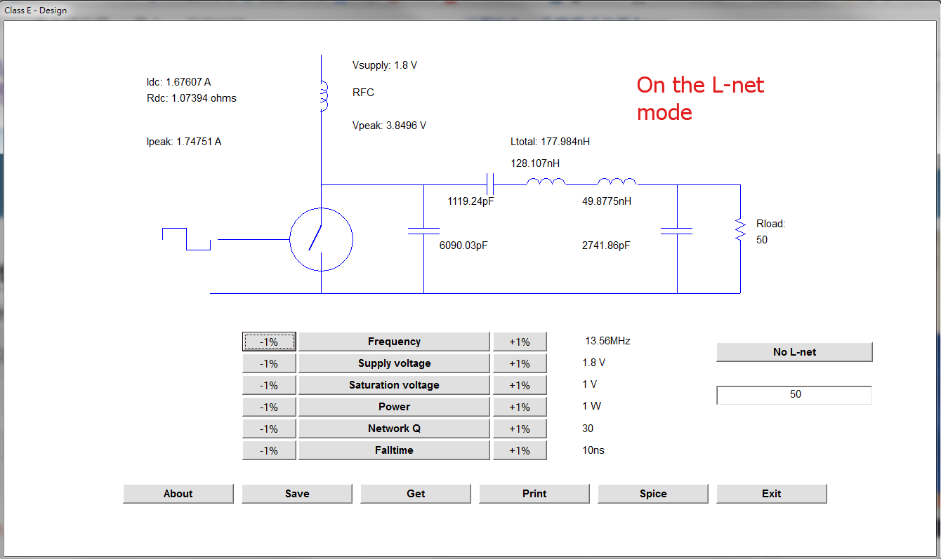
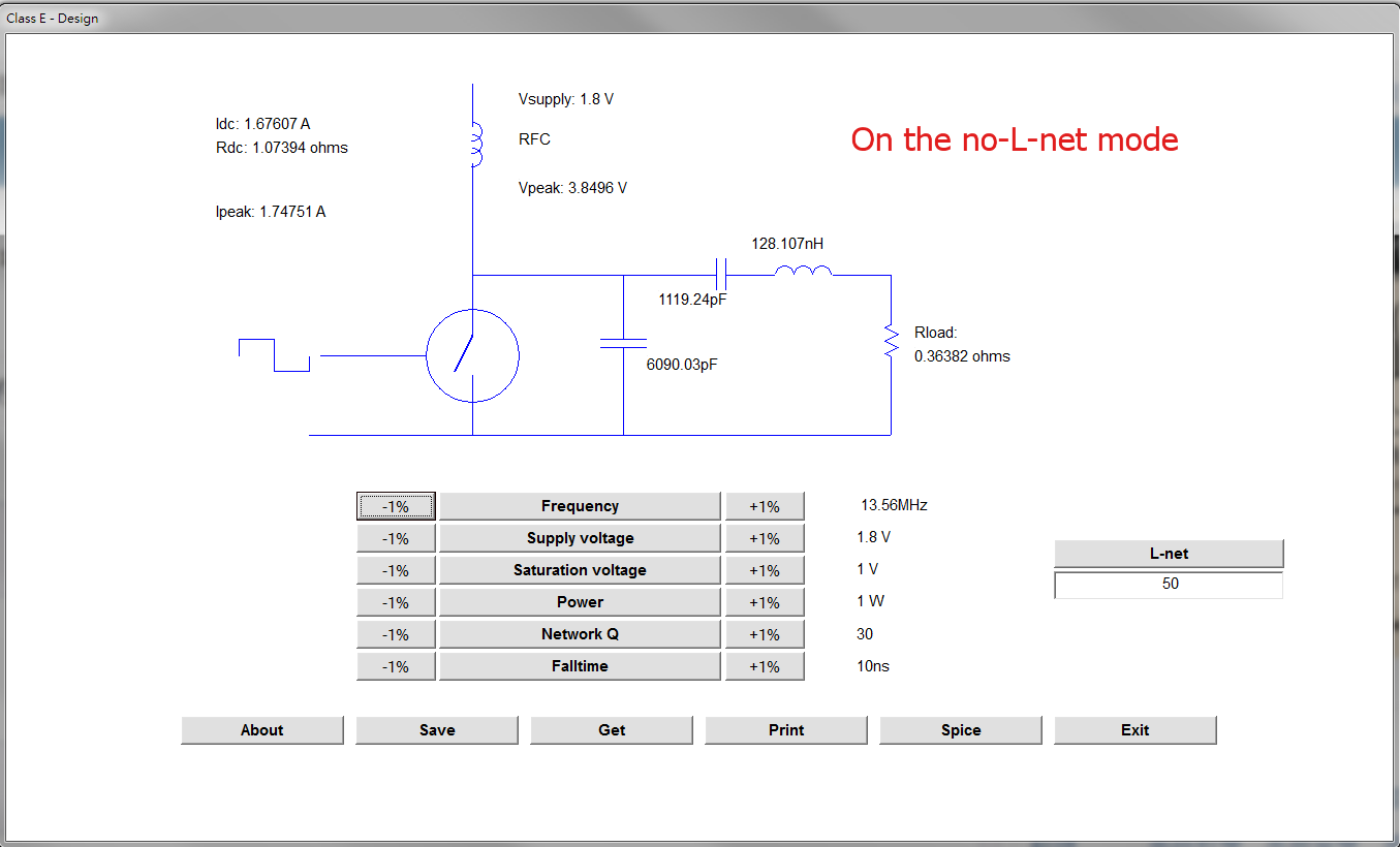
The above two images show the difference in the corresponding mode.
Does 50 ohm of Rload in the L-net mode acts as the internal resistance of the measurement equipment?
Does 0.36382 ohm of Rload in the No L-net mode acts as the parasitic resistance of the antenna coil which shown as an inductor with 128.107nH?
Any help is highly appreciated.
best regard,
Joseph
Have anyone ever used this tutorial widget of class E amplifier design?
(you can get it easy by google the keyword "tonnesoftware")
I don't understand lots of parameters which should be filled in the blank for completing the circuit design.
I hope that anyone could discuss the following listed parameter with me.
Saturation voltage: Does that just mean that the minimum voltage at drain node to ensure the transistor operated at saturation region. If I am right, how to evaluate the threshold voltage precisely of switching transistor?
Network Q : Does that mean the Q factor of sole series RLC. The Q could be expressed as equation 1/R*(L/C)^0.5.
Falltime : I don't have any ideal what's the influence of this parameter in class e amplifier design.
If I am wrong, please correct me.
Beside that, I found that there are two selection modes on the right side( either No L-net or L-net)


What's the main difference by these two options?
The above two images show the difference in the corresponding mode.
Does 50 ohm of Rload in the L-net mode acts as the internal resistance of the measurement equipment?
Does 0.36382 ohm of Rload in the No L-net mode acts as the parasitic resistance of the antenna coil which shown as an inductor with 128.107nH?
Any help is highly appreciated.
best regard,
Joseph
