Calculate input and output impedance at microwave office
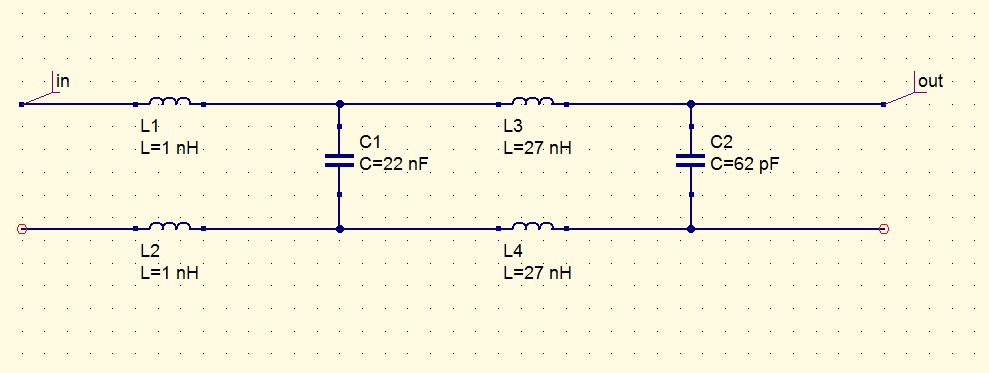
I want to ask how I can calculate the input and output impedance of an existing filter with microwave office. The input and output of the filter are differential. You can see the filter in the following picture. The filter is low pass and and I think has a cut off frequency
Connect a Ideal Transformer to each port ( so one side will be differentially connected to the ports, other side one pin will be grounded, other pin will be connected 50 Ohm Port element ) and do a s-parameter simulation and look at input/output impedances on the smith chart.
There should also be Differential-to-Single Ended Converter component but I don't remember.Refer to Help..
This is the MMCONV element.
I don't really understand cause I am new to this. Could you explain in more detail what I have to do please. Also it would be really great if someone could this calculations for me.
It's a library component.Search it in Help index.You'll find information about that..
With a value of C1=22nF the 3dB cut-off frequency of the LPF is about 300 kHz.
I think the value should be 22pF, and the 3dB cut-off frequency will be about 150 MHz.
Sorry about that the value of the capacitor is indeed 22pF. Would it be difficult for you to make this calculation for input and output impedance and send me the numbers-figures from 0 to 200Mhz. I've made some calculations but I am not sure if they are correct.
input Calculate impedance 相关文章:
- Different Input/Output matching
- How do you choose input power while doing loadpull?
- Why an input inductor required in all GPS LNA?
- Input and output impedance matching in Distributed amplifier
- In distributed amplifiers, is it total input capacitance of the gain stage or Cgs
- curve fitting for input and output matching